|
|
Application module:
Via component |
ISO/TS 10303-1754:2010-03(E)
© ISO
|
This clause specifies the information requirements for the
Via component
application module. The information requirements are specified as the
Application Reference Model (ARM) of this application module.
NOTE 1 A graphical representation of the information
requirements is given in
Annex C.
NOTE 2 The mapping specification is specified in
5.1. It shows how
the information requirements are met by using common resources and
constructs defined or imported in the MIM schema of this application
module.
The following EXPRESS specification begins the
Via_component_arm
schema and identifies the necessary external references.
EXPRESS specification:
         *)

            SCHEMA Via_component_arm;
(*
The following EXPRESS interface statements specify the elements
imported from the ARMs of other application modules.
EXPRESS specification:
*)

            USE FROM
            Interconnect_module_connection_routing_arm;
               --
            ISO/TS 10303-1684
            USE FROM
            Layered_interconnect_module_design_arm;
               --
            ISO/TS 10303-1698
(*
NOTE 1
The schemas referenced above are specified in the following
part of ISO 10303:
| Interconnect_module_connection_routing_arm |
ISO/TS 10303-1684 |
| Layered_interconnect_module_design_arm |
ISO/TS 10303-1698 |
NOTE 2
See Annex C,
Figures
C.1and C.2
for a graphical representation of this schema.
This subclause specifies the ARM entities for this
module. Each ARM application entity is an atomic element that
embodies a unique application concept and contains attributes
specifying the data elements of the entity. The ARM
entities and definitions are specified below.
A Blind_via is a type of
Via.
Each Blind_via is either a
Non_conductive_base_blind_via,
or a
Plated_conductive_base_blind_via.
Blind_via is defined in IEC 60050-541.
EXAMPLE
Figure 1 illustrates an idealized cross-section of an interconnect substrate,
showing the depth of penetration of a Blind_via into the substrate.
The Blind_vias in this example are filled with resin extruded from the dielectric
Stratum
represented with a cross-hatch pattern.
Figure 1 — Blind via
EXPRESS specification:
            *)

            ENTITY Blind_via

              ABSTRACT SUPERTYPE

            OF (ONEOF (Non_conductive_base_blind_via,
                                Plated_conductive_base_blind_via))

              SUBTYPE OF (Via);

            END_ENTITY;
(*
A Buried_via is a type of Via. Buried_via is defined in IEC 60050-541.
EXAMPLE
Figure 2 illustrates a Buried_via in a cross-section view
of an interconnect substrate.
The Buried_via in this example is filled by standard material processing;
in this case excess resin from the dielectric
Stratum
represented with a cross-hatch pattern.
Figure 2 — Buried via
EXPRESS specification:
            *)

            ENTITY Buried_via

              SUBTYPE OF (Via);

            END_ENTITY;
(*
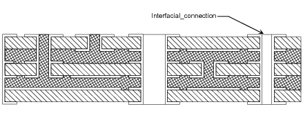
An Interfacial_connection is a type of Via that has both ends visible in
the printed circuit board. Interfacial_connection is defined in IEC 60050-541.
EXAMPLE
Figure 3 illustrates an Interfacial_connection in a cross-section view of a substrate.
The Interfacial_connection in this example is not filled.
Figure 3 — Interfacial connection
EXPRESS specification:
            *)

            ENTITY Interfacial_connection

              SUBTYPE OF (Via);

            END_ENTITY;
(*
A Non_conductive_base_blind_via is a type of Blind_via with a
floor whose material is non-conductive.
EXPRESS specification:
            *)

            ENTITY Non_conductive_base_blind_via

              SUBTYPE OF (Blind_via);

            END_ENTITY;
(*
A Plated_conductive_base_blind_via is a type of Blind_via in
which the material that composes the floor of the Blind_via is conductive, and in which the floor material
of the Blind_via is contiguous with the material on the wall of the Blind_via. The process that is to create
this conductive contiguous material is electroplating or similar.
EXPRESS specification:
            *)

            ENTITY Plated_conductive_base_blind_via

              SUBTYPE OF (Blind_via);

            END_ENTITY;
(*
This subclause specifies the ARM subtype constraint for
this module. The subtype constraint places a constraint on the
possible super-type / subtype instantiations.
The ARM subtype constraint and definition is
specified below.
The
via_subtypes
constraint specifies a constraint that applies to instances of subtypes of
Via.
EXPRESS specification:
            *)
SUBTYPE_CONSTRAINT via_subtypes FOR Via;

              ONEOF (Blind_via,
         Buried_via,
         Interfacial_connection);

            END_SUBTYPE_CONSTRAINT;
(*
         *)

         END_SCHEMA;  -- Via_component_arm
(*
© ISO 2009 — All rights reserved


