| Integrated application resource: Draughting | ISO 10303-101:2021(E) © ISO |
The subjects of the draughting_element_schema are the basic draughting elements used on drawings to convey information about the product being depicted. Text using draughting-specific fonts and character sets is used to convey product and product-processing requirements and to make references to other requirements documents. Curves with draughting-specific thicknesses (widths) and dash patterns are used to clarify the depiction of a product shape. Images of the shape are annotated with curves representing feature centres, path of motion, and location of cutting planes. The draughting activity also uses many symbols to convey requirements for characteristics such as surface texture and welds. These draughting curves, text, and symbols are often combined to form a complete presentation of a requirement and are referred to as a draughting callout.
Draughting often applies a requirement to a specific area of the depicted product shape. In such instances other draughting curves, such as leader lines, projection lines, and dimension lines, are used to direct the requirement to the place of application.
This schema specifies the basic draughting elements and their combinations used to annotate the depicted product shape and convey information regarding interpretation of the drawing.
This clause defines the information requirements to which implementations shall conform using the EXPRESS language as defined in ISO 10303-11. The following EXPRESS declaration begins the draughting_element_schema and identifies the necessary external references.Each implementation of an AP that uses this schema and that encodes entity names shall use the encoding specified in Annex A. Each reference to this schema in an open system shall use the identifier encoding specified in Annex B. This schema is illustrated in Annex D using the EXPRESS-G notation.
EXPRESS specification:
         *)

            	SCHEMA draughting_element_schema;
            REFERENCE FROM
            geometric_model_schema

               --
            ISO 10303-42
  (geometric_set,


            tessellated_geometric_set);
            REFERENCE FROM
            geometry_schema

               --
            ISO 10303-42
  (axis2_placement,


            axis2_placement_2d,


            axis2_placement_3d,


            cartesian_point,


            geometric_representation_item,


            plane);
            REFERENCE FROM
            mechanical_design_schema

               --
            ISO 10303-113
  (annotation_placeholder_occurrence);
            REFERENCE FROM
            presentation_appearance_schema

               --
            ISO 10303-46
  (invisible_item,


            presentation_style_assignment,


            styled_item);
            REFERENCE FROM
            presentation_definition_schema

               --
            ISO 10303-46
  (annotation_occurrence,


            annotation_curve_occurrence,


            annotation_fill_area_occurrence,


            annotation_text_occurrence,


            annotation_symbol_occurrence);
            REFERENCE FROM
            presentation_organization_schema

               --
            ISO 10303-46
  (annotation_representation_select,


            area_dependent_annotation_representation,


            camera_model,


            presentation_area,


            presentation_view,


            view_dependent_annotation_representation);
            REFERENCE FROM
            presentation_resource_schema

               --
            ISO 10303-46
  (planar_box);
            REFERENCE FROM
            product_property_definition_schema

               --
            ISO 10303-41
  (product_definition_shape,


            property_definition,


            shape_aspect,


            shape_aspect_relationship);
            REFERENCE FROM
            product_property_representation_schema

               --
            ISO 10303-41
  (item_identified_representation_usage,


            shape_definition_representation);
            REFERENCE FROM
            representation_schema

               --
            ISO 10303-43
  (representation,


            representation_item,


            mapped_item,


            representation_map,


            using_representations);
            REFERENCE FROM
            support_resource_schema

               --
            ISO 10303-41
  (label,


            text,


            bag_to_set);
            REFERENCE FROM
            topology_schema

               --
            ISO 10303-42
  (face_surface);

(*
NOTE 1 The schemas referenced above are specified in the following parts:
geometric_model_schema ISO 10303-42 geometry_schema ISO 10303-42 mechanical_design_schema ISO 10303-113 presentation_appearance_schema ISO 10303-46 presentation_definition_schema ISO 10303-46 presentation_organization_schema ISO 10303-46 presentation_resource_schema ISO 10303-46 product_property_definition_schema ISO 10303-41 product_property_representation_schema ISO 10303-41 representation_schema ISO 10303-43 support_resource_schema ISO 10303-41 topology_schema ISO 10303-42
NOTE 2 See Annex D for a graphical representation of this schema.
The draughting activity, regardless of the engineering discipline, specializes generic annotation curves, symbols, and text. The specialization of annotation curves is based on the need to identify certain curves according to existing draughting standards. Further, the specialization makes it possible to assign curve presentation styles according to those same standards. The specialization of generic annotation text is based on the draughting need to specify draughting-specific fonts and character sets. The specialization of generic annotation symbols is based on the need for draughting symbols to be comprised of draughting-specific curves and text.
The three most common draughting-specific annotation curves are the dimension line, leader line, and projection line (also known as an extension line or witness line). These draughting annotation curves are not limited to their stated geometric type. A leader line referring to a feature on a drawing, such as a dimension, object, or outline, is really a series of one-to-many curve segments, not necessarily line segments. This fact is also true of the projection line and dimension line.
Dimension lines, leader lines, and projection lines can be shared by more than one callout.
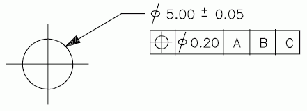
EXAMPLE 1 A single instance of a leader line can be used to direct (refer) a callout, containing a dimension value and tolerance, while also directing a second callout, containing a geometric tolerance of location, to the same feature of size (see Figure 2).
Dimension lines and leader lines cannot exist independently of a callout. Only the projection line can exist independently (without directing a callout).
A callout directed by means of both a leader line and a projection line is both a leader-directed callout and a projection-directed callout.

A terminator symbol (e.g., arrowhead) is another concept of existing draughting-practices standards. A terminator symbol may be used to terminate a leader line, or it may be used to show the extent of the dimension and the direction of measurement when placed along a dimension line. Although referred to as an arrow or arrowhead, some draughting practices standards specify other symbols, such as a dot, box, or slash to terminate a leader line or indicate a dimension extent. Therefore, this concept has been generalized as a terminator symbol.
A draughting callout is a collection of draughting- or presentation-specific annotation curves, text, and symbols depicting information or requirements about the product or drawing itself. This part of ISO 10303 supports callouts which may contain text, symbols, or curves that are directed to a feature (a place on a drawing) by a leader line, a projection line, a dimension line, or a combination of these. A callout whose text, symbols, or curves are directed by means of both a leader line and a projection line is both a leader-directed callout and a projection callout.
A leader line is a draughting element that may be explicitly provided or may be an annotation_placeholder_leader_line that only consist of a list of points with an associated optional terminator symbol. The terminator symbols for the annotation_placeholder_leader_line are defined by the des_apll_point_symbol enumeration type. An annotation_placeholder_occurrence_with_leader_line aggregates one or more annotation_placeholder_leader_line to provide data necessary to render needed leader lines associated with a specific annotation occurrence.
EXAMPLE 2 An annotation_placeholder_occurrence_with_leader_line specifies two annotation_placeholder_leader_lines, one of which is an annotation_to_model_leader_line, illustrated in Figure 3, and the other of which is an auxiliary_leader_line, illustrated in Figure 4, to provide location data for a placeholder for presentation of a geometric tolerance. The point list for Figure 3 is (A1, A2, A3) while that for Figure 4 is (B1, B2, B3).
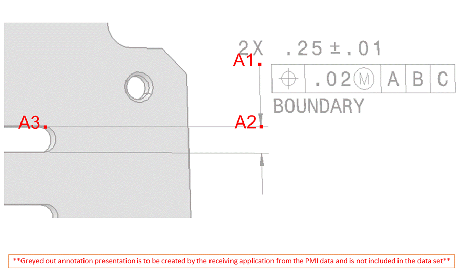
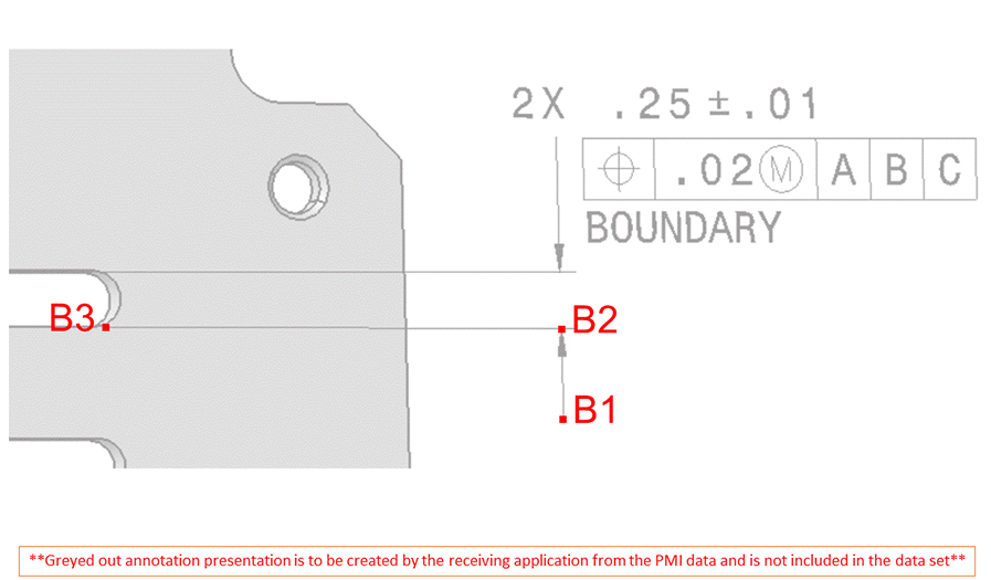
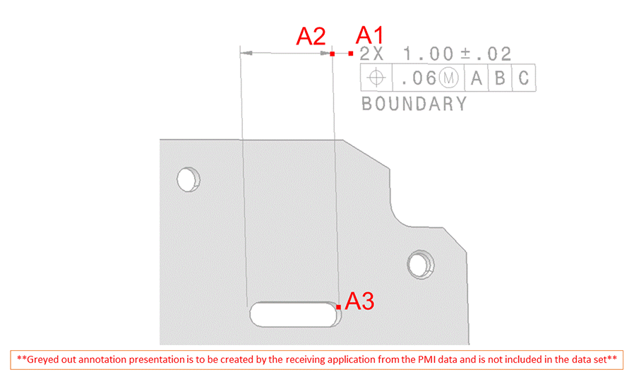
EXAMPLE 3 An annotation_placeholder_occurrence_with_leader_line specifies two annotation_to_model_leader_line, one of which is illustrated in Figure 5, and the other illustrated in Figure 6, to provide location data for a placeholder for presentation of a geometric tolerance. The point list for Figure 5 is (A1, A2, A3) while that for Figure 6 is (B1, B2, B3, B4).
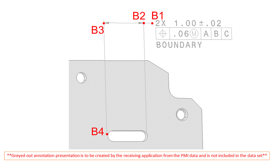
Draughting Application Protocols may further specialize resources found in this schema or in ISO 10303-46 to obtain draughting concepts not explicitly provided.

EXPRESS specification:
            *)

            TYPE
            annotation_plane_element
            =


            SELECT

               (draughting_callout,
    styled_item);

            END_TYPE;

            (*

NOTE The list of entity data types will be extended in application resources that use the constructs of this resource.
EXPRESS specification:
            *)

            TYPE
            des_annotation_representation_select
            =

            EXTENSIBLE

            GENERIC_ENTITY


            SELECT
            BASED_ON
            annotation_representation_select
            WITH


               (draughting_model);

            END_TYPE;

            (*

EXPRESS specification:
            *)

            TYPE
            des_apll_point_select
            =


            SELECT

               (apll_point,
    apll_point_with_surface);

            END_TYPE;

            (*

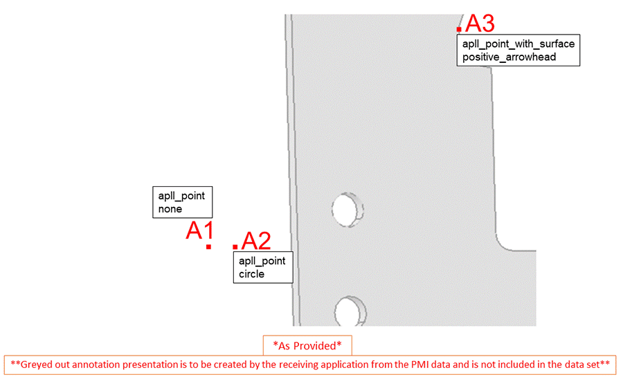
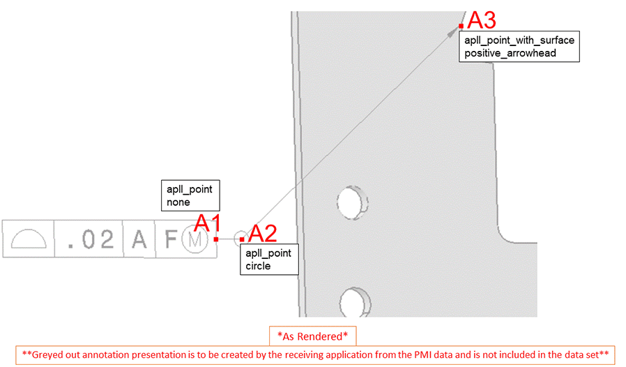
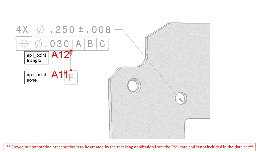
NOTE 1 The actual graphic of the symbol is not provided, but the interpretation shall be in accordance with applicable draughting standards. In Figures 7 through 11 the first line of text in the rectangular box identifies the type of apll_point illustrated and the second line identifies the value of the des_apll_point_symbol applied to that point in the data set.
EXPRESS specification:
            *)

            TYPE
            des_apll_point_symbol
            =

            ENUMERATION

            OF


            (circle,
    dot,
    internal_pair_forward_arrowhead,
    internal_pair_reverse_arrowhead,
    none,
    positive_arrowhead,
    triangle);

            END_TYPE;

            (*
Enumerated item definitions:
circle: a circle is to be applied to the point specified in the leader line.
NOTE 2 Figure 7 illustrates the 'as provided' data for the application of a circle to a leader line. The point list for Figure 7 is (A1, A2, A3).
NOTE 3 Figure 8 illustrates the 'as rendered' presentation for the application of a circle to a leader line. The point list for Figure 8 is (A1, A2, A3).
dot: a dot is to be applied to the point specified in the leader line.
internal_pair_forward_arrowhead: an internal_pair_forward_arrowhead is one end of a pair of arrows where there is no annotation between the arrows. Forward is to be interpreted as the leader line arrives to the point. The arrowhead is at a point with an index in the list of points that is greater than the point to which the internal_pair_reverse_arrowhead is applied.
NOTE 4 Figure 9 illustrates the 'as rendered' presentation for the application of both the internal pair forward and reverse arrowheads to a leader line. The point list for Figure 9 is (B1, B2, B3, B4).
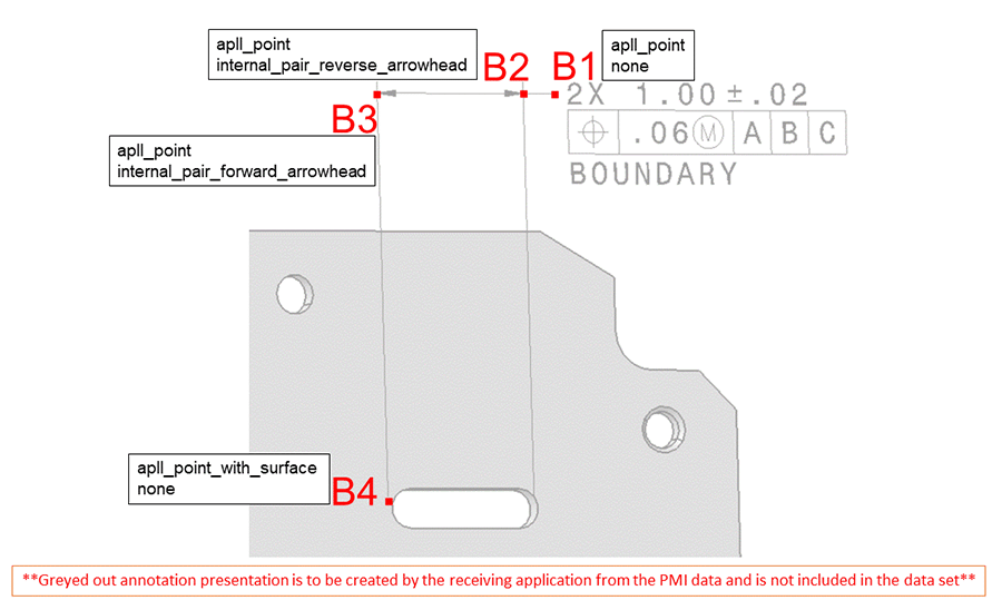
internal_pair_reverse_arrowhead: an internal_pair_reverse_arrowhead is one end of a pair of arrows where there is no annotation between the arrows. Reverse is to be interpreted as the leader line leaves the point. The arrowhead is at a point with an index in the list of points that is less than the point to which the internal_pair_forward_arrowhead is applied.
none: there is no symbol applied.
positive_arrowhead: a positive_arrowhead is applied to a point where the index of the point in the list of points is greater than the index of the first point in the list.
NOTE 5 Figure 10 illustrates the 'as rendered' presentation for the application of a positive arrowhead to a leader line.The point list for Figure 10 is (A1, A2, A3).
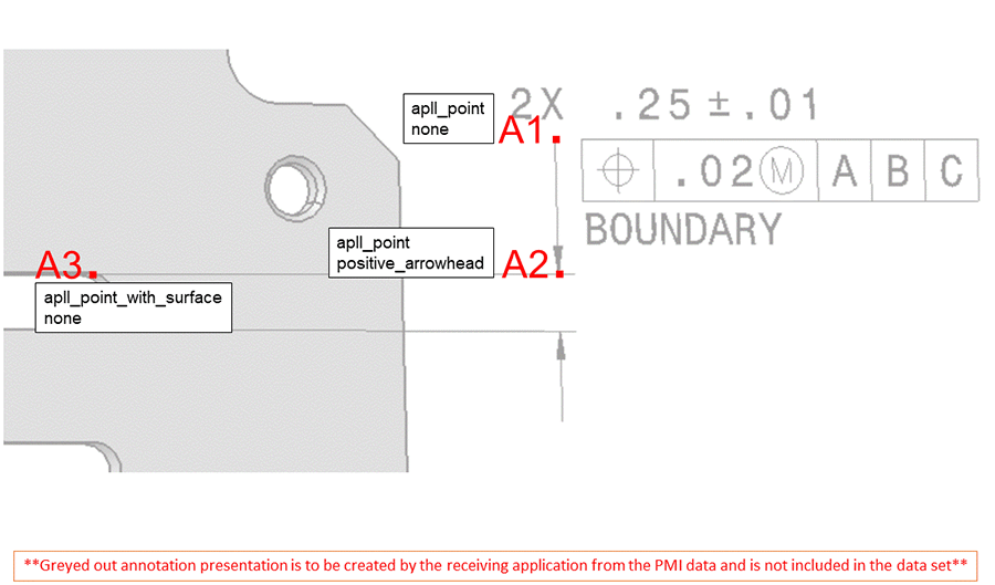
triangle: a triangle is applied to a point where the index of the point in the list of points is greater than the index of the first point in the list.
NOTE 6 A triangle is applied to the last element in the list of points in most industrial date exchange scenarios.
NOTE 7 Figure 11 illustrates the 'as rendered' presentation for the application of a triangle to a leader line between two annotation elements. The point list for Figure 11 is (A11, A12).

NOTE The list of entity data types will be extended in application resources that use the constructs of this resource.
EXPRESS specification:
            *)

            TYPE
            des_invisible_item
            =

            EXTENSIBLE

            GENERIC_ENTITY


            SELECT
            BASED_ON
            invisible_item
            WITH


               (draughting_callout);

            END_TYPE;

            (*

EXPRESS specification:
            *)

            TYPE
            dimension_extent_usage
            =

            ENUMERATION

            OF


            (origin,
    target);

            END_TYPE;

            (*
Enumerated item definitions:
origin: the beginning of the dimension.
target: the end of the dimension.

NOTE The list of entity data types will be extended in application resources that use the constructs of this resource.
A draughting_callout_element is either draughting text, symbols, fill area, or curves which are a part of a draughting callout. A draughting_callout_element may be extended in applications that use this resource.EXPRESS specification:
            *)

            TYPE
            draughting_callout_element
            =

            EXTENSIBLE

            GENERIC_ENTITY


            SELECT

               (annotation_curve_occurrence,
    annotation_fill_area_occurrence,
    annotation_symbol_occurrence,
    annotation_text_occurrence,
    tessellated_annotation_occurrence);

            END_TYPE;

            (*

EXPRESS specification:
            *)

            TYPE
            draughting_model_item_association_select
            =


            SELECT

               (annotation_occurrence,
    draughting_callout);

            END_TYPE;

            (*

NOTE The list of entity data types will be extended in application resources that use the constructs of this resource.
EXPRESS specification:
            *)

            TYPE
            draughting_model_item_definition
            =

            EXTENSIBLE

            GENERIC_ENTITY


            SELECT

               (product_definition_shape,
    property_definition,
    shape_aspect,
    shape_aspect_relationship);

            END_TYPE;

            (*

EXPRESS specification:
            *)

            TYPE
            draughting_model_item_select
            =


            SELECT

               (mapped_item,
    styled_item,
    axis2_placement,
    camera_model,
    draughting_callout);

            END_TYPE;

            (*

EXPRESS specification:
            *)

            TYPE
            plane_or_planar_box
            =


            SELECT

               (plane,
    planar_box);

            END_TYPE;

            (*

NOTE The role of an annotation_placeholder_leader_line is to provide a simplified representation for leader line.
EXAMPLE An annotation contains a graphic relating a datum feature symbol to a datum reference frame. An annotation_to_annotation_leader_line provides a simplified representation for the graphic.
EXPRESS specification:
            *)

            ENTITY annotation_placeholder_leader_line

              ABSTRACT SUPERTYPE

            OF (ONEOF (annotation_to_annotation_leader_line,
                                annotation_to_model_leader_line,
                                auxiliary_leader_line))

              SUBTYPE OF (geometric_representation_item);


              geometric_elements : LIST[2:?] OF
            UNIQUE
            des_apll_point_select;
DERIVE

              model_end : des_apll_point_select := geometric_elements[HIINDEX(geometric_elements)];
INVERSE

              container : annotation_placeholder_occurrence_with_leader_line FOR leader_line;
UNIQUE

              UR1: geometric_elements;

            END_ENTITY;
(*
Attribute definitions:
geometric_elements: specifies the list of points for the simplified representation.
model_end: specifies the terminus of the annotation_placeholder_leader_line that is on, or near, the surface of the product model, or is on a dimension line, or on a curve attached to a dimension line, or to an extension line, or is on another annotation that is more directly connected to the product model.
container: an inverse relationship that specifies that the existence of the annotation_placeholder_leader_line is dependent on the existence of the annotation_placeholder_occurrence_with_leader_line that specifies the annotation_placeholder_leader_line as a member of its leader_line.
Formal propositions:
UR1: No more than one member of annotation_placeholder_leader_line shall reference a specific aggregate of geometric_elements.

EXPRESS specification:
            *)

            ENTITY annotation_placeholder_occurrence_with_leader_line

              SUBTYPE OF (annotation_placeholder_occurrence);


              leader_line : SET[1:?] OF annotation_placeholder_leader_line;
UNIQUE

              UR1: leader_line;

            END_ENTITY;
(*
Attribute definitions:
leader_line: specifies the set of annotation_placeholder_leader_line that comprise the leader line contents.
Formal propositions:
UR1: No more than one member of annotation_placeholder_occurrence_with_leader_line shall reference a specific aggregate leader_line.

NOTE A receiving system may need to project leader lines to the relevant plane.
An annotation_plane may satisfy the requirements for an annotation plane specified in ISO 16792 when all the members of elements are intended to be on the same plane and only numeric accuracy prevents the data from being co-planar.
EXPRESS specification:
            *)

            ENTITY annotation_plane

              SUBTYPE OF (annotation_occurrence, geometric_representation_item);


              elements :
            OPTIONAL
            SET[1:?] OF annotation_plane_element;


              SELF\styled_item.item : plane_or_planar_box;
WHERE

              WR1: SELF\geometric_representation_item.dim = 3;

              WR2: NOT('PRESENTATION_RESOURCE_SCHEMA.'+'PLANAR_BOX' IN TYPEOF(SELF\styled_item.item)) OR
            ('GEOMETRY_SCHEMA.'+'AXIS2_PLACEMENT_3D' IN TYPEOF(SELF\styled_item.item\planar_box.placement));

              WR3: (('PRESENTATION_RESOURCE_SCHEMA.'+'PLANAR_BOX' IN TYPEOF(SELF\styled_item.item)) AND
            ('PRESENTATION_APPEARANCE_SCHEMA.'+'CURVE_STYLE' IN TYPEOF(SELF\styled_item.styles[1]\presentation_style_assignment.styles[1])))
            OR
            (('GEOMETRY_SCHEMA.'+'PLANE' IN TYPEOF(SELF\styled_item.item)) AND
            ('PRESENTATION_APPEARANCE_SCHEMA.'+'FILL_AREA_STYLE' IN TYPEOF(SELF\styled_item.styles[1]\presentation_style_assignment.styles[1])));

              WR4: (SIZEOF(SELF\styled_item.styles) = 1) AND
            (SIZEOF(SELF\styled_item.styles[1]\presentation_style_assignment.styles) = 1);

            END_ENTITY;
(*
Attribute definitions:
elements: the annotation_plane_elements that are within the annotation_plane.
item: the plane_or_planar_box that is styled by the annotation_plane.
Formal propositions:
WR1: An annotation_plane shall be defined in 3D space.
WR2: If item is a planar_box then it shall be placed by an axis2_placement_3d.
WR3: Allowed styles are fill_area_style for plane and fill_area_style or curve_style for planar_box.
WR4: An annotation_plane shall have exactly one style.
Informal propositions:
IP1: The elements should be located in the definition plane.
NOTE Because of numerical inaccuracy this might not be perfectly the case. A receiving system may correct such a deviation.

EXPRESS specification:
            *)

            ENTITY annotation_to_annotation_leader_line

              SUBTYPE OF (annotation_placeholder_leader_line);
DERIVE

              start_end : des_apll_point_select := SELF\annotation_placeholder_leader_line.geometric_elements[1];
WHERE

              WR1: (SIZEOF (['DRAUGHTING_ELEMENT_SCHEMA.APLL_POINT_WITH_SURFACE'] * TYPEOF(SELF\annotation_placeholder_leader_line.model_end))
            = 0) AND
            (SIZEOF (['DRAUGHTING_ELEMENT_SCHEMA.APLL_POINT_WITH_SURFACE'] * TYPEOF(start_end)) = 0);

            END_ENTITY;
(*
Attribute definitions:
start_end: specifies the first element of the attribute geometric_elements inherited from annotation_placeholder_leader_line.
Formal propositions:
WR1: Each annotation_to_annotation_leader_line starts and ends on a curve.

EXPRESS specification:
            *)

            ENTITY annotation_to_model_leader_line

              SUBTYPE OF (annotation_placeholder_leader_line);
DERIVE

              start_end : des_apll_point_select := SELF\annotation_placeholder_leader_line.geometric_elements[1];
WHERE

              WR1: SIZEOF (['DRAUGHTING_ELEMENT_SCHEMA.APLL_POINT_WITH_SURFACE'] * TYPEOF(SELF\annotation_placeholder_leader_line.model_end))
            = 1;

              WR2: SIZEOF (['DRAUGHTING_ELEMENT_SCHEMA.APLL_POINT_WITH_SURFACE'] * TYPEOF(start_end)) = 0;

            END_ENTITY;
(*
Attribute definitions:
start_end: specifies the first element of the attribute geometric_elements inherited from annotation_placeholder_leader_line.
Formal propositions:
WR1: An annotation_to_model_leader_line shall end on the product model.
WR2: The geometric_elements inherited from annotation_placeholder_leader_line shall not start on the part model.

EXPRESS specification:
            *)

            ENTITY apll_point

              SUBTYPE OF (cartesian_point);


              symbol_applied : des_apll_point_symbol;
INVERSE

              container : annotation_placeholder_leader_line FOR geometric_elements;
WHERE

              WR1: SIZEOF(['DRAUGHTING_ELEMENT_SCHEMA.APLL_POINT_WITH_SURFACE'] * TYPEOF(SELF)) = 0;

              WR2: SIZEOF(USEDIN(SELF, 'GEOMETRY_SCHEMA.GEOMETRIC_SET.ELEMENTS')) = 0;

            END_ENTITY;
(*
Attribute definitions:
symbol_applied: specifies the symbol to be applied to the apll_point.
container: an inverse relationship that specifies that the existence of the apll_point is dependent on the existence of the annotation_placeholder_leader_line that specifies the apll_point as a member of its geometric_elements.
Formal propositions:
WR1: No member of apll_point shall also be a member of apll_point_with_surface.
WR2: No member of apll_point shall be referenced by the geometric_set referenced by item.

NOTE In industrial practice it is common to terminate the simplified leader line representation with an apll_point_with_surface.
EXPRESS specification:
            *)

            ENTITY apll_point_with_surface

              SUBTYPE OF (cartesian_point);


              symbol_applied : des_apll_point_symbol;


              associated_surface : face_surface;
INVERSE

              container : annotation_placeholder_leader_line FOR geometric_elements;
WHERE

              WR1: SIZEOF(['DRAUGHTING_ELEMENT_SCHEMA.APLL_POINT'] * TYPEOF(SELF)) = 0;

              WR2: SIZEOF(USEDIN(SELF, 'GEOMETRY_SCHEMA.GEOMETRIC_SET.ELEMENTS')) = 0;

            END_ENTITY;
(*
Attribute definitions:
symbol_applied: specifies the symbol to be applied to the apll_point_with_surface.
associated_surface: specifies the surface that is the logical target for the simplified representation of a leader line that points to a product model.
container: an inverse relationship that specifies that the existence of the apll_point_with_surface is dependent on the existence of the annotation_placeholder_leader_line that specifies the apll_point_with_surface as a member of its geometric_elements.
Formal propositions:
WR1: No member of apll_point_with_surface shall also be a member of apll_point.
WR2: No member of apll_point_with_surface shall be referenced by the geometric_set referenced by item.

EXPRESS specification:
            *)

            ENTITY auxiliary_leader_line

              SUBTYPE OF (annotation_placeholder_leader_line);


              controlling_leader_line : annotation_to_model_leader_line;
DERIVE

              free_space_end : des_apll_point_select := SELF\annotation_placeholder_leader_line.geometric_elements[1];
WHERE

              WR1: SELF\annotation_placeholder_leader_line.container :=: controlling_leader_line\annotation_placeholder_leader_line.container;

              WR2: SIZEOF (['DRAUGHTING_ELEMENT_SCHEMA.APLL_POINT_WITH_SURFACE'] * TYPEOF(free_space_end)) = 0;

              WR3: SIZEOF (['DRAUGHTING_ELEMENT_SCHEMA.APLL_POINT_WITH_SURFACE'] * TYPEOF(SELF\annotation_placeholder_leader_line.model_end))
            = 1;

            END_ENTITY;
(*
Attribute definitions:
controlling_leader_line: specifies the annotation_to_model_leader_line that controls this auxiliary_leader_line.
free_space_end: specifies the first element of the attribute geometric_elements inherited from annotation_placeholder_leader_line which is a point at an arbitrary location.
Formal propositions:
WR1: An auxiliary_leader_line shall be associated to the annotation_placeholder_occurrence_with_leader_line that is associated to the controlling_leader_line.
WR2: The geometric_elements inherited from annotation_placeholder_leader_line shall not start on annotation nor shall it start on the part model.
WR3: The geometric_elements inherited from annotation_placeholder_leader_line shall end on the part model.

A dimension_curve shall satisfy the requirements for a dimension line specified in ISO 129-1.
A dimension_curve is used in a dimension_curve_directed_callout to direct the other elements of the callout to the presentation of the dimensioned feature or features.
NOTE 1 Various forms of the dimension curve, also known as a dimension line, with their related terminator symbols are shown in Figure 12. Dimension curves are combined with other draughting annotation curves (e.g., extension lines), text, and symbols to form dimension_curve_directed_callout and dimension_graphs.

NOTE 2 Although the dimension_curve is generally thin and continuous in nature, it may be broken for the insertion of the dimension text and symbols, making the dimension_curve appear as two leader lines. A break in the dimension_curve is possible through use of resources provided by ISO 10303-46.
EXPRESS specification:
            *)

            ENTITY dimension_curve

              SUBTYPE OF (annotation_curve_occurrence);
WHERE

              WR1: (SIZEOF(
            QUERY(dct <* USEDIN(SELF,'DRAUGHTING_ELEMENT_SCHEMA.' +
            'TERMINATOR_SYMBOL.ANNOTATED_CURVE')
            | (('DRAUGHTING_ELEMENT_SCHEMA.'+
            'DIMENSION_CURVE_TERMINATOR' IN TYPEOF(dct))
            ))
            ) <= 2);

              WR2: SIZEOF(
            QUERY( dcdc <* USEDIN(SELF,'DRAUGHTING_ELEMENT_SCHEMA.' +
            'DRAUGHTING_CALLOUT.CONTENTS') |
            ('DRAUGHTING_ELEMENT_SCHEMA.'+
            'DIMENSION_CURVE_DIRECTED_CALLOUT' IN TYPEOF(dcdc)))
            )>= 1;

              WR3: (SIZEOF(
            QUERY(dct1 <* USEDIN(SELF,'DRAUGHTING_ELEMENT_SCHEMA.' +
            'TERMINATOR_SYMBOL.ANNOTATED_CURVE')
            | (('DRAUGHTING_ELEMENT_SCHEMA.'+
            'DIMENSION_CURVE_TERMINATOR' IN TYPEOF(dct1))
            AND (dct1\dimension_curve_terminator.role = dimension_extent_usage.origin)))
            ) <= 1)
            AND
            (SIZEOF(
            QUERY (dct2 <* USEDIN(SELF,'DRAUGHTING_ELEMENT_SCHEMA.'+
            'TERMINATOR_SYMBOL.ANNOTATED_CURVE')
            | (('DRAUGHTING_ELEMENT_SCHEMA.'+
            'DIMENSION_CURVE_TERMINATOR' IN TYPEOF(dct2))
            AND (dct2\dimension_curve_terminator.role = dimension_extent_usage.target)))
            ) <= 1);

            END_ENTITY;
(*
Formal propositions:
WR1: There may be zero, one, or two dimension_curve_terminators annotating a dimension_curve.
WR2: A dimension_curve shall be used by at least one referencing dimension_curve_directed_callout.
NOTE 3 A dimension_curve is used to direct information to the dimensioned feature or features. Curves which do not meet this requirement should be treated as annotation curves with referencing terminator_symbols.
WR3: A dimension_curve shall not be annotated with more than one terminator_symbol indicating the origin of a dimension extent, nor shall a dimension_curve be annotated with more than one terminator_symbol indicating the target of a dimension extent.

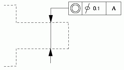
NOTE 1 A draughting_callout for a geometric tolerance may be directed to the presentation of the toleranced feature by means of a dimension line. An example of a dimension curve directed callout is shown in Figure 13.
NOTE 2 Generally, a dimension_curve for a dimension_curve_directed_callout is also the dimension_curve for a dimension_graph.
EXPRESS specification:
            *)

            ENTITY dimension_curve_directed_callout

              SUBTYPE OF (draughting_callout);
WHERE

              WR1: SIZEOF(QUERY(d_c<*SELF\draughting_callout.contents |
            'DRAUGHTING_ELEMENT_SCHEMA.DIMENSION_CURVE' IN (TYPEOF(d_c))))<=2;

              WR2: SIZEOF(SELF\draughting_callout.contents) >= 2;

            END_ENTITY;
(*
Formal propositions:
WR1: A dimension_curve_directed_callout shall have exactly one dimension_curve in the set of draughting_callout_elements.
WR2: A dimension_curve_directed_callout shall contain some annotation other than the required dimension_curve.

EXPRESS specification:
            *)

            ENTITY dimension_curve_terminator

              SUBTYPE OF (terminator_symbol);


              role : dimension_extent_usage;
WHERE

              WR1: 'DRAUGHTING_ELEMENT_SCHEMA.DIMENSION_CURVE' IN TYPEOF
            (SELF\terminator_symbol.annotated_curve);

            END_ENTITY;
(*
Attribute definitions:
role: the role of the dimension_curve_terminator as a dimension origin or target in the presentation of the dimension extent being graphed.
NOTE A dimension_curve_terminator in the role of origin is located with respect to a point on the dimension line, generally corresponding to the beginning or start of a dimension. A dimension_curve_terminator in the role of target is located with respect to a point on the dimension line, generally corresponding to the end of a dimension. Where a dimension_curve_terminator is to correspond with the dimension_graph_projection_curve_usage, the same role should be assigned to both with respect to the extent of the dimension_graph.
Formal propositions:
WR1: Each dimension_curve_terminator shall annotate a dimension_curve.

A draughting_callout is classified by the type of curve that directs information within the draughting_callout or by its contents that present product requirements such as dimension measurements.
A draughting_callout may contain text, symbols, and curves which are directed to a place of interest on the drawing by means of a leader line, projection line, dimension line, or a combination of these. A draughting_callout that includes a leader line to direct the eye of the reader to a place of interest is a leader_directed_callout. A draughting_callout that includes a projection line to direct the eye of the reader to a place of interest is a projection_directed_callout. A draughting_callout that includes a dimension line to direct information in the callout is a dimension_curve_directed_callout.
If the draughting_callout is to present a product requirement about a known dimension measurement, it is a dimension_callout.
EXPRESS specification:
            *)

            ENTITY draughting_callout

              SUBTYPE OF (geometric_representation_item);


              contents : SET[1:?] OF draughting_callout_element;
WHERE

              WR1: (SIZEOF (QUERY (l_1 <* SELF\draughting_callout.contents |
            'DRAUGHTING_ELEMENT_SCHEMA.LEADER_CURVE' IN (TYPEOF(l_1)))) = 0) OR
            ('DRAUGHTING_ELEMENT_SCHEMA.LEADER_DIRECTED_CALLOUT' IN (TYPEOF(SELF))) AND
            (SIZEOF (QUERY (l_1 <* SELF\draughting_callout.contents |
            'DRAUGHTING_ELEMENT_SCHEMA.PROJECTION_CURVE' IN (TYPEOF(l_1)))) = 0) OR
            ('DRAUGHTING_ELEMENT_SCHEMA.PROJECTION_DIRECTED_CALLOUT' IN (TYPEOF(SELF))) AND
            (SIZEOF (QUERY (l_1 <* SELF\draughting_callout.contents |
            'DRAUGHTING_ELEMENT_SCHEMA.DIMENSION_CURVE' IN (TYPEOF(l_1)))) = 0) OR
            ('DRAUGHTING_ELEMENT_SCHEMA.DIMENSION_CURVE_DIRECTED_CALLOUT' IN (TYPEOF(SELF)));

              WR2: SIZEOF (QUERY ( apo <* contents |
            'MECHANICAL_DESIGN_SCHEMA.ANNOTATION_PLACEHOLDER_OCCURRENCE' in TYPEOF(apo)
            )) < 2;

            END_ENTITY;
(*
Attribute definitions:
contents: the annotation curves, symbols, or text comprising the presentation of information.
Formal propositions:
WR1: A draughting callout that includes a leader line shall be a leader_directed_callout. A draughting callout that includes a projection line shall be a projection_directed_callout. A draughting callout that includes a dimension line shall be a dimension dimension_curve_directed_callout.
WR2: There shall be no more than one annotation_placeholder_occurrence in draughting_callout.

NOTE 1 This entity, in conjunction with the draughting_callout entity, is based on the relationship template that is described in ISO 10303-41.
EXPRESS specification:
            *)

            ENTITY draughting_callout_relationship;


              name : label;


              description : text;


              relating_draughting_callout : draughting_callout;


              related_draughting_callout : draughting_callout;

            END_ENTITY;
(*
Attribute definitions:
name: the word or group of words by which the draughting_callout_relationship is spoken of or referred to.
description: the text that relates the nature of the draughting_callout_relationship.
relating_draughting_callout: one of the draughting_callouts which is a part of the relationship.
EXAMPLE 1 If the draughting_callout_relationship is a relationship between a leader directed dimension and a geometric tolerance frame (see Figure 2), the relating draughting_callout may be the leader directed dimension for a feature of size.
NOTE 2 The role of this attribute is defined in the application protocol or the ISO 10303 integrated resource that uses or specializes this entity.
related_draughting_callout: the other draughting_callout which is a part of the relationship.
EXAMPLE 2 In a leader directed dimension with a related geometric tolerance frame (see Figure 2) the related_draughting_callout may be the geometric tolerance frame, where the geometric tolerance frame is being referred to the feature of size via the leader directed dimension.
NOTE 3 The role of this attribute is defined in the application protocol or the ISO 10303 integrated resource that uses or specializes this entity.

EXPRESS specification:
            *)

            ENTITY draughting_model

              SUBTYPE OF (representation);


              SELF\representation.items : SET[1:?] OF draughting_model_item_select;
UNIQUE

              UR1: SELF\representation.name;
WHERE

              WR1: SIZEOF (QUERY (mi <* QUERY (it <* SELF.items |
            ('REPRESENTATION_SCHEMA.MAPPED_ITEM' IN TYPEOF(it))) |
            NOT (
            SIZEOF (['PRODUCT_PROPERTY_REPRESENTATION_SCHEMA.SHAPE_REPRESENTATION',
            'DRAUGHTING_ELEMENT_SCHEMA.DRAUGHTING_MODEL'] *
            TYPEOF (mi\mapped_item.mapping_source.
            mapped_representation)) = 1
            ))) = 0;

              WR2: SIZEOF (QUERY (smi <* QUERY (si <* QUERY (it <* SELF.items |
            ('PRESENTATION_APPEARANCE_SCHEMA.STYLED_ITEM' IN TYPEOF(it))) |
            ('REPRESENTATION_SCHEMA.MAPPED_ITEM' IN
            TYPEOF(si\styled_item.item))) |
            (NOT (('PRODUCT_PROPERTY_REPRESENTATION_SCHEMA.SHAPE_REPRESENTATION' IN
            TYPEOF(smi\styled_item.item\mapped_item.
            mapping_source.mapped_representation))
            AND
            (SIZEOF (QUERY (sty <* smi\styled_item.styles |
            (NOT (SIZEOF (QUERY (psa <* sty.styles |
            (NOT ('PRESENTATION_APPEARANCE_SCHEMA.CURVE_STYLE' IN TYPEOF(psa))))) = 1
            )))) = 1)))
            )) = 0;

            END_ENTITY;
(*
Attribute definitions:
items: the set of draughting_model_item_select.
Formal propositions:
UR1: The representation.name shall be unique.
WR1: Each item of a draughting_model shall be a mapped_item, styled_item, axis2_placement, or camera_model.
WR2: If there is a mapped_item in the draughting_model, the source of the mapped_item shall be a shape_representation or another draughting_model.

EXAMPLE In an application protocol, an instance of the shape_representation describes a characteristic of a product. One element of the shape_representation - a Curve - represents the boundary of a hole that is a shape_aspect in the product. This entity data type may be used to state that the curve describes the hole, in the context of the entire shape_representation describing the shape of the product.
EXPRESS specification:
            *)

            ENTITY draughting_model_item_association

              SUBTYPE OF (item_identified_representation_usage);


              SELF\item_identified_representation_usage.definition : draughting_model_item_definition;


              SELF\item_identified_representation_usage.used_representation : annotation_representation_select;


              SELF\item_identified_representation_usage.identified_item : draughting_model_item_association_select;

            END_ENTITY;
(*
Attribute definitions:
definition: specifies the product_definition_shape, property_definition, shape_aspect, shape_aspect_relationship that is presented by the identified_item.
used_representation: specifies the area_dependent_annotation_representation, presentation_area, presentation_view, symbol_representation, view_dependent_annotation_representation containing the identified_item.
identified_item: specifies the annotation_occurrence, draughting_callout presenting the definition.

A leader_curve shall satisfy the requirements for a leader line specified in ISO 129-1.
A leader_curve is used in a leader_directed_callout to direct the other elements of the callout to an intended place or point of interest on a drawing.
NOTE 1 Generally, a leader_curve, also known as a leader line, is a continuous thin single or multiple segment curve with a terminator symbol at one end, indicating the place of interest. Various forms of the leader curve are shown in Figure 14. Style requirements are specified in other international and national draughting practices standards.

EXPRESS specification:
            *)

            ENTITY leader_curve

              SUBTYPE OF (annotation_curve_occurrence);
WHERE

              WR1: SIZEOF(
            QUERY(ldc <* USEDIN( SELF, 'DRAUGHTING_ELEMENT_SCHEMA.' +
            'DRAUGHTING_CALLOUT.CONTENTS')
            |   'DRAUGHTING_ELEMENT_SCHEMA.' +
            'LEADER_DIRECTED_CALLOUT'  IN TYPEOF(ldc))) >= 1;

            END_ENTITY;
(*
Formal propositions:
WR1: A leader_curve shall be used by at least one referencing leader_directed_callout.
NOTE 2 A leader_curve always directs other information contained within a draughting_callout to a place on a drawing. Curves which do not meet this requirement should be treated as annotation curves with a referencing terminator symbol.

NOTE An example of a leader directed callout is given in Figure 15.

EXPRESS specification:
            *)

            ENTITY leader_directed_callout

              SUBTYPE OF (draughting_callout);
WHERE

              WR1: SIZEOF (QUERY (l_1 <* SELF\draughting_callout.contents |
            'DRAUGHTING_ELEMENT_SCHEMA.LEADER_CURVE' IN (TYPEOF(l_1)))) >= 1;

              WR2: SIZEOF(SELF\draughting_callout.contents) >=2;

            END_ENTITY;
(*
Formal propositions:
WR1: A leader_directed_callout shall have at least one leader_curve in the set of draughting_callout_elements.
WR2: A leader_directed_callout shall contain some annotation other than the required leader_curve.

EXPRESS specification:
            *)

            ENTITY leader_terminator

              SUBTYPE OF (terminator_symbol);
WHERE

              WR1: 'DRAUGHTING_ELEMENT_SCHEMA.LEADER_CURVE' IN TYPEOF
            (SELF\terminator_symbol.annotated_curve);

            END_ENTITY;
(*
Formal propositions:
WR1: A leader_terminator shall annotate a leader_curve.

NOTE 1 A projection_curve, also known as projection line, extension line, or witness line, generally has a presentation style which is thin and continuous. To accommodate various draughting practices, no restriction on presentation style has been made.provides an example of the use of two projection curves.
A projection_curve shall satisfy the requirements for an extension line specified in ISO 129-1.
NOTE 2 Figure 16 provides two examples of projection_curves. Both projection_curves extend a surface to locations beyond the outline of the depicted part. A projection curve may be combined with other curves, text, and symbols to form a projection_directed_callout.

NOTE 3 Although a projection_curve is generally not presented as a dashed pattern, it may have an invisible segment where it crosses an arrowhead. This characteristic is made possible through the use of resources provided by ISO 10303-46.
EXPRESS specification:
            *)

            ENTITY projection_curve

              SUBTYPE OF (annotation_curve_occurrence);

            END_ENTITY;
(*

NOTE An example of a projection_directed_callout is shown in Figure 17. In this figure a callout, representing a surface tolerance requirement, is directed to the surface by a projection curve, representing an extension of the surface.

EXPRESS specification:
            *)

            ENTITY projection_directed_callout

              SUBTYPE OF (draughting_callout);
WHERE

              WR1: SIZEOF(QUERY(p_1<*SELF\draughting_callout.contents |
            'DRAUGHTING_ELEMENT_SCHEMA.PROJECTION_CURVE' IN (TYPEOF(p_1))))<=2;

              WR2: SIZEOF(SELF\draughting_callout.contents) >=2;

            END_ENTITY;
(*
Formal propositions:
WR1: A projection_directed_callout shall have exactly one projection_curve in the set of draughting_callout_elements.
WR2: A projection_directed_callout shall contain some annotation other than the required projection_curve.

NOTE A terminator_symbol such as an arrow, may also be used to indicate a direction of interest (e.g., measuring direction of a dimension line or viewing direction for a line indicating the cutting plane of a section view).
A terminator_symbol shall satisfy the requirements for a terminator specified in ISO 129-1.
EXPRESS specification:
            *)

            ENTITY terminator_symbol

              SUBTYPE OF (annotation_symbol_occurrence);


              annotated_curve : annotation_curve_occurrence;

            END_ENTITY;
(*
Attribute definitions:
annotated_curve: the curve being annotated by the terminator_symbol.

EXPRESS specification:
            *)

            ENTITY tessellated_annotation_occurrence

              SUBTYPE OF (annotation_occurrence);


              SELF\styled_item.item : tessellated_geometric_set;

            END_ENTITY;
(*
Attribute definitions:
item: the tessellated_geometric_set that is styled by the tessellated_annotation_occurrence.

The annotation_curve_subtypes constraint specifies a constraint that applies to instances of subtypes of annotation_curve_occurrence.
An annotation_curve_subtypes is a constraint that applies to instances of subtypes of annotation_curve_occurrence.EXPRESS specification:
            *)
SUBTYPE_CONSTRAINT annotation_curve_subtypes FOR annotation_curve_occurrence;

              ONEOF (dimension_curve,
         leader_curve,
         projection_curve);

            END_SUBTYPE_CONSTRAINT;
(*
         *)

         END_SCHEMA;  -- draughting_element_schema
(*
© ISO 2021 — All rights reserved