|
|
Application module:
Draughting annotation |
ISO/TS 10303-1206:2014-02(E)
© ISO
|
This clause specifies the information requirements for the
Draughting annotation
application module. The information requirements are specified as the
Application Reference Model (ARM) of this application module.
NOTE 1 A graphical representation of the information
requirements is given in
Annex C.
NOTE 2 The mapping specification is specified in
5.1. It shows how
the information requirements are met by using common resources and
constructs defined or imported in the MIM schema of this application
module.
This clause defines the information requirements to which implementations shall
conform using the EXPRESS language as defined in ISO 10303-11.
The following begins the
Draughting_annotation_arm
schema and identifies the necessary external references.
EXPRESS specification:
         *)

            SCHEMA Draughting_annotation_arm;
(*
The following EXPRESS interface statement specifies the elements
imported from the ARM of another application module.
EXPRESS specification:
*)

            USE FROM
            Draughting_element_arm;
               --
            ISO/TS 10303-1310
(*
NOTE 1
The schemas referenced above are specified in the following
part of ISO 10303:
| Draughting_element_arm |
ISO/TS 10303-1310 |
NOTE 2
See Annex C,
Figures
C.1and C.2
for a graphical representation of this schema.
This subclause specifies the ARM types
for this application module. The ARM types and
definitions are specified below.
The da_draughting_callout_content_select type is an extension
of the
draughting_callout_content_select type.
It adds the data
types
Annotation_subfigure
and
Annotation_symbol
to the list of alternate data types.
EXPRESS specification:
            *)

            TYPE
            da_draughting_callout_content_select =


            SELECT
            BASED_ON
            draughting_callout_content_select
            WITH


               (Annotation_subfigure,
    Annotation_symbol);

            END_TYPE;

            (*
The symbol_definition_select type allows for the designation of the data
types
Dimension_symbol, General_symbol, Geometric_tolerance_symbol, Marker, Surface_condition_symbol
and
Terminator.
EXPRESS specification:
            *)

            TYPE
            symbol_definition_select =


            SELECT

               (Dimension_symbol,
    General_symbol,
    Geometric_tolerance_symbol,
    Marker,
    Surface_condition_symbol,
    Terminator);

            END_TYPE;

            (*
This subclause specifies the ARM entities for this
module. Each ARM application entity is an atomic element that
embodies a unique application concept and contains attributes
specifying the data elements of the entity. The ARM
entities and definitions are specified below.
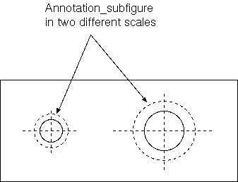
An Annotation_subfigure is a type of
Annotation_element.
An Annotation_subfigure is the occurrence of a template that contains annotation elements.
EXAMPLE
Figure 1
depicts an Annotation_subfigure.
Figure 1 — Annotation subfigure for a hole on a technical drawing
EXPRESS specification:
            *)

            ENTITY Annotation_subfigure

              SUBTYPE OF (Annotation_element);

            END_ENTITY;
(*
An Annotation_symbol is a type of
Annotation_element.
An Annotation_symbol is an annotation presenting a symbol.
EXPRESS specification:
            *)

            ENTITY Annotation_symbol

              SUBTYPE OF (Annotation_element);


              symbol_definition : symbol_definition_select;

            END_ENTITY;
(*
Attribute definitions:
symbol_definition:
specifies the
symbol_definition_select
that defines this annotation.
A Dimension_curve_terminator is a type of
Terminator_symbol.
EXPRESS specification:
            *)

            ENTITY Dimension_curve_terminator

              SUBTYPE OF (Terminator_symbol);

            END_ENTITY;
(*
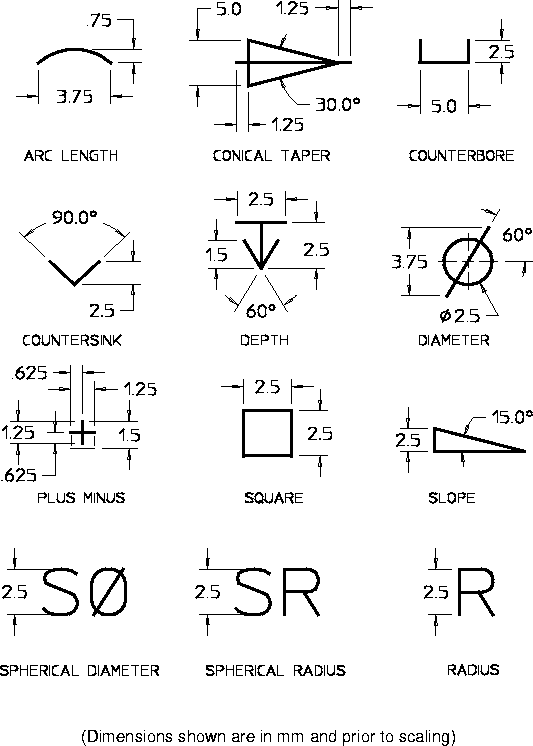
An Dimension_symbol is a predefined annotation symbol used to present information about dimensions.
This AP supports the dimension symbols shown in
figure 2.
Figure 2 — Predefined dimension symbols
EXPRESS specification:
            *)

            ENTITY Dimension_symbol;

            END_ENTITY;
(*
An General_symbol is a type of
Representation.
An General_symbol is the definition of a symbol that is either user-defined or externally defined.
EXPRESS specification:
            *)

            ENTITY General_symbol

              SUBTYPE OF (Representation);

            END_ENTITY;
(*
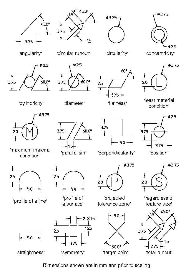
An Geometric_tolerance_symbol is a predefined annotation symbol used to present information about a geometric tolerance.
This AP supports the geometric tolerance symbols defined in ISO 7083, i.e., 'angularity', 'basic dimension', 'blanked datum
reference',
'circular runout', 'circularity', 'concentricity', 'cylindricity', 'datum target identification', 'filled datum reference',
'flatness',
'maximum material condition', 'parallelism', 'perpendicularity', 'position', 'profile of a line', 'profile of a surface',
'projected tolerance zone', 'straightness', 'symmetry', and 'total runout'.
Additionally, symbols for 'diameter', 'least material condition', 'regardless of feature size', and 'target point' are supported.
The dimensions of the symbols are presented in
figure 3.
Figure 3 — Predefined geometrical tolerlance symbols
EXPRESS specification:
            *)

            ENTITY Geometric_tolerance_symbol;

            END_ENTITY;
(*
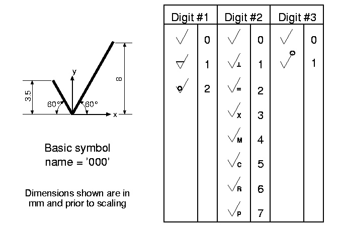
An Surface_condition_symbol is a pre-defined annotation symbol used to present information about surface conditions.
This part of ISO 10303 supports the surface condition symbols defined in ISO 1302.
These symbols are, in the context of this AP, identified by a three digit code as shown on
figure 4.
Figure 4 — Pre-defined surface condition symbols
EXPRESS specification:
            *)

            ENTITY Surface_condition_symbol;

            END_ENTITY;
(*
An Terminator_symbol is a type of
Annotation_symbol.
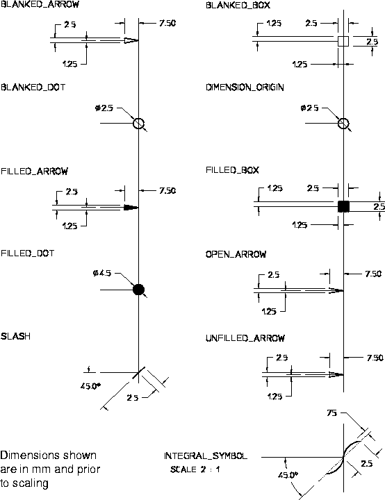
An Terminator_symbol is a predefined annotation symbol used to present a line terminator.
This AP supports the terminator symbols shown in
figure 5.
Figure 5 — Predefined terminator symbols
EXPRESS specification:
            *)

            ENTITY Terminator_symbol

              SUBTYPE OF (Annotation_symbol);

            END_ENTITY;
(*
This subclause specifies the ARM subtype constraint for
this module. The subtype constraint places a constraint on the
possible super-type / subtype instantiations.
The ARM subtype constraint and definition is
specified below.
The
alternate_annotation_elements
constraint specifies a constraint that applies to instances of subtypes of
Annotation_element.
EXPRESS specification:
            *)
SUBTYPE_CONSTRAINT alternate_annotation_elements FOR Annotation_element;

              ONEOF (Annotation_subfigure,
         Annotation_symbol,
         Fill_area);

            END_SUBTYPE_CONSTRAINT;
(*
         *)

         END_SCHEMA;  -- Draughting_annotation_arm
(*
© ISO 2014 — All rights reserved


