|
|
Application module:
Draughting element |
ISO/TS 10303-1310:2021(E)
© ISO
|
This clause specifies the information requirements for the
Draughting element
application module. The information requirements are specified as the
Application Reference Model (ARM) of this application module.
NOTE 1 A graphical representation of the information
requirements is given in
Annex C.
NOTE 2 The mapping specification is specified in
5.1. It shows how
the information requirements are met by using common resources and
constructs defined or imported in the MIM schema of this application
module.
This clause defines the information requirements to which implementations shall
conform using the EXPRESS language as defined in ISO 10303-11.
The following begins the
Draughting_element_arm
schema and identifies the necessary external references.
EXPRESS specification:
         *)

            SCHEMA Draughting_element_arm;
(*
The following EXPRESS interface statements specify the elements
imported from the ARMs of other application modules.
EXPRESS specification:
*)

            USE FROM
            Associative_text_arm;
               --
            ISO/TS 10303-1132
            USE FROM
            Curve_appearance_arm;
               --
            ISO/TS 10303-1003
(*
NOTE 1
The schemas referenced above are specified in the following
part of ISO 10303:
| Associative_text_arm |
ISO/TS 10303-1132 |
| Curve_appearance_arm |
ISO/TS 10303-1003 |
NOTE 2
See Annex C,
Figures
C.1and C.2
for a graphical representation of this schema.
This subclause specifies the ARM types
for this application module. The ARM types and
definitions are specified below.
The annotation_plane_element type allows for the designation of the data
types
Draughting_callout and Styled_element.
EXPRESS specification:
            *)

            TYPE
            annotation_plane_element =


            SELECT

               (Draughting_callout,
    Styled_element);

            END_TYPE;

            (*
The de_appearance_select type is an extension
of the
appearance_select type.
It adds the data
types
Curve_appearance, Point_appearance, and Text_style
to the list of alternate data types.
EXPRESS specification:
            *)

            TYPE
            de_appearance_select =


            SELECT
            BASED_ON
            appearance_select
            WITH


               (Curve_appearance,
    Point_appearance,
    Text_style);

            END_TYPE;

            (*
The draughting_callout_content_select type is an
extensible list of alternate data types
that allows for the designation of the data
types Annotation_curve and Annotation_text_occurrence.
NOTE
The list of entity data types may be
extended in application modules that use the constructs of
this module.
EXPRESS specification:
            *)

            TYPE
            draughting_callout_content_select =

            EXTENSIBLE

            GENERIC_ENTITY


            SELECT

               (Annotation_curve,
    Annotation_text_occurrence);

            END_TYPE;

            (*
The plane_or_planar_box type allows for the designation of the data
types
Planar_box and Plane.
EXPRESS specification:
            *)

            TYPE
            plane_or_planar_box =


            SELECT

               (Planar_box,
    Plane);

            END_TYPE;

            (*
This subclause specifies the ARM entities for this
module. Each ARM application entity is an atomic element that
embodies a unique application concept and contains attributes
specifying the data elements of the entity. The ARM
entities and definitions are specified below.
An Annotation_fill_area is a type of
Detailed_geometric_model_element.
The area of an Annotation_fill_area is bounded by a set of planar, non-intersecting and non-self-intersecting closed curves.
The area may be filled with hatching, shading, colour, or tiling.
EXPRESS specification:
            *)

            ENTITY Annotation_fill_area

              SUBTYPE OF (Detailed_geometric_model_element);


              boundaries : SET[1:?] OF Curve;

            END_ENTITY;
(*
Attribute definitions:
boundaries:
a set of closed
Curves
that define the inner and outer boundaries of the fill area.
There shall exist at least one
Curve
for the Annotation_fill_area.
An Annotation_plane is a type of
Annotation_element
for the purpose of grouping annotation elements within a 3D coordinate space.
The plane may be bounded by a rectangle and styled so that it becomes visible.
The interpretation for text in the plane shall be that x axis is the “line that is being written on”, indicating the reading
direction. The
interpretation shall be that the y axis points upward from the base to the top of the characters. The
interpretation shall be that the z axis points towards the reader. Elements referenced by Annotation_plane shall be in planes
that are parallel to the Annotation_plane with the exception of leader lines which need not be parallel to the
Annotation_plane.
NOTE
In the case of leader lines that are not parallel to the Annotation_plane the receiving system may need to project them to the relevant plane.
An Annotation_plane may satisfy the requirements for an annotation plane specified in ISO 16792
when all the members of elements are intended to be on the same plane and only numeric accuracy prevents the
data from being co-planar.
EXPRESS specification:
            *)

            ENTITY Annotation_plane

              SUBTYPE OF (Annotation_element);


              elements :
            OPTIONAL
            SET[1:?] OF annotation_plane_element;


              SELF\Styled_element.element : plane_or_planar_box;

            END_ENTITY;
(*
Attribute definitions:
elements:
specifies a role of the
annotation_plane_element
for the Annotation_plane.
There shall exist one or more
annotation_plane_elements
for the Annotation_plane.
The value of this attribute need not be specified.
element:
an attribute inherited from the
Styled_element
shall be redeclared as the
plane_or_planar_box
for the Annotation_plane.
A Dimension_curve is a type of
Annotation_curve.
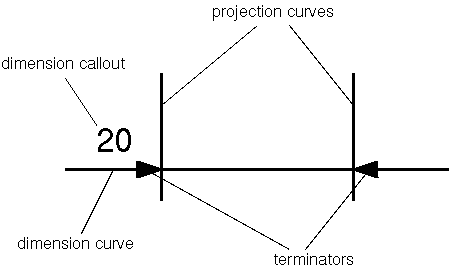
A Dimension_curve is a curve that is used for the graphical representation of a dimension.
If necessary, it includes the additional symbology needed to show the extent of the dimension.
EXAMPLE
Figure 1
shows the use of a Dimension_curve in a drawing.
Figure 1 — Components of a dimension in a drawing
EXPRESS specification:
            *)

            ENTITY Dimension_curve

              SUBTYPE OF (Annotation_curve);


              terminator : SET[0:2] OF Terminator;

            END_ENTITY;
(*
Attribute definitions:
terminator:
specifies the
Terminator
for the Dimension_curve.
There shall exist not more than two
Terminators
for the Dimension_curve.
A Dimension_curve_directed_callout is a type of
Draughting_callout
directed by a
Dimension_curve
to a presented element of the product shape.
EXPRESS specification:
            *)

            ENTITY Dimension_curve_directed_callout

              SUBTYPE OF (Draughting_callout);


              dimension_curve : Dimension_curve;
WHERE

              WR1: dimension_curve IN SELF\Draughting_callout.contents;

            END_ENTITY;
(*
Attribute definitions:
dimension_curve:
the dimension line of the draughting callout.
Formal propositions:
WR1:
The dimension_curve must be in the list of items defined in attribute
contents.
A Draughting_callout is a type of
Representation_item.
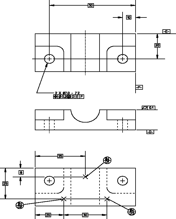
A Draughting_callout is a human-interpretable collection of annotation curves, symbols, and text that presents product
requirements or information used to interpret the drawing.
A Draughting_callout may be either a
Dimension_curve_directed_callout
or a
Leader_directed_callout
or a
Projection_directed_callout.
EXAMPLE
Figure 2
shows typical Draughting_callout objects on a drawing.
Figure 2 — Draughting callouts on a drawing
EXPRESS specification:
            *)

            ENTITY Draughting_callout

              SUPERTYPE OF (ONEOF (Dimension_curve_directed_callout,
                       Leader_directed_callout,
                       Projection_directed_callout))

              SUBTYPE OF (Representation_item);


              contents : LIST[1:?] OF draughting_callout_content_select;

            END_ENTITY;
(*
Attribute definitions:
contents:
specifies the
draughting_callout_content_select
that form the Draughting_callout.
There shall exist one or more
draughting_callout_content_select
for the Draughting_callout.
A Fill_area is a type of
Annotation_element.
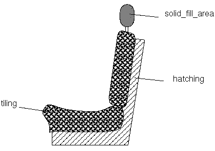
A Fill_area is a bounded area containing colouring, hatching, or tiling.
NOTE
A Fill_area communicates some aspect of a physical part characteristic or distinguishes it from its surroundings.
EXAMPLE
Figure 3
depicts some fill area styles.
Figure 3 — Fill area styles
EXPRESS specification:
            *)

            ENTITY Fill_area

              SUBTYPE OF (Annotation_element);


              SELF\Styled_element.element : Annotation_fill_area;


              reference_point : Point;

            END_ENTITY;
(*
Attribute definitions:
element:
an attribute inherited from the
Styled_element
shall be redeclared as the
Annotation_fill_area
for the Fill_area.
reference_point:
specifies a point within the fill area, used in the placement and initiation of the fill area appearance.
The reference point is a point through that a line of a hatching pattern shall pass or at which the origin of a tile shall
be located.
The reference point also establishes the point at which the first visible segment of a line font used as the curve appearance
for
a hatching pattern starts.
A Generic_annotation_curve is a type of
Annotation_curve.
EXPRESS specification:
            *)

            ENTITY Generic_annotation_curve

              SUBTYPE OF (Annotation_curve);

            END_ENTITY;
(*
A Leader is a type of
Annotation_curve.
A Leader directs a dimension, a note, or a symbol to the intended place on an element of geometry or annotation.
NOTE
The concept of Leader is incompletely modeled in the ARM for some use cases.
Complete specification can be obtained in the definition of the MIM entities annotation_to_annotation_leader_line,
annotation_to_model_leader_line, and auxiliary_leader_line.
EXPRESS specification:
            *)

            ENTITY Leader

              SUBTYPE OF (Annotation_curve);

            END_ENTITY;
(*
A Leader_directed_callout is a type of
Draughting_callout
that is directed by a
Leader
curve.
EXPRESS specification:
            *)

            ENTITY Leader_directed_callout

              SUBTYPE OF (Draughting_callout);


              leader : Leader;
WHERE

              WR1: leader IN SELF\Draughting_callout.contents;

            END_ENTITY;
(*
Attribute definitions:
leader:
the leader curve that directs the draughting callout.
Formal propositions:
WR1:
The leader must be in the list of items defined in attribute
contents.
A Projection_curve is a type of
Annotation_curve.
A Projection_curve is the extension of a point, line, surface, or theoretical point of intersection to a location outside the part outline.
EXPRESS specification:
            *)

            ENTITY Projection_curve

              SUBTYPE OF (Annotation_curve);

            END_ENTITY;
(*
A Projection_directed_callout is a type of
Draughting_callout
that is directed by a
Projection_curve.
EXPRESS specification:
            *)

            ENTITY Projection_directed_callout

              SUBTYPE OF (Draughting_callout);


              projection_curve : Projection_curve;
WHERE

              WR1: projection_curve IN SELF\Draughting_callout.contents;

            END_ENTITY;
(*
Attribute definitions:
projection_curve:
the projection curve that directs the draughting callout.
Formal propositions:
WR1:
The projection_curve must be in the list of items defined in attribute
contents.
This subclause specifies the ARM subtype constraint for
this module. The subtype constraint places a constraint on the
possible super-type / subtype instantiations.
The ARM subtype constraint and definition is
specified below.
The
annotation_curve_subtypes
constraint specifies a constraint that applies to instances of
Annotation_curve
and enforces the rule that its subtypes
Leader, Projection_curve and Dimension_curve
are exclusive.
EXPRESS specification:
            *)
SUBTYPE_CONSTRAINT annotation_curve_subtypes FOR Annotation_curve;

              (ONEOF (Leader,
          Projection_curve,
          Dimension_curve)
  ANDOR Generic_annotation_curve);

            END_SUBTYPE_CONSTRAINT;
(*
         *)

         END_SCHEMA;  -- Draughting_element_arm
(*
© ISO 2021 — All rights reserved


