|
|
Application module:
Edge shape feature |
ISO/TS 10303-1673:2006(E)
© ISO
|
This clause specifies the information requirements for the
Edge shape feature
application module. The information requirements are specified as the
Application Reference Model (ARM) of this application module.
NOTE 1 A graphical representation of the information
requirements is given in
Annex C.
NOTE 2 The mapping specification is specified in
5.1. It shows how
the information requirements are met by using common resources and
constructs defined or imported in the MIM schema of this application
module.
The following EXPRESS specification begins the
Edge_shape_feature_arm
schema and identifies the necessary external references.
EXPRESS specification:
         *)

            SCHEMA Edge_shape_feature_arm;
(*
The following EXPRESS interface statements specify the elements
imported from the ARMs of other application modules.
EXPRESS specification:
*)

            USE FROM
            Layered_3d_shape_arm;
               --
            ISO/TS 10303-1694
            USE FROM
            Characteristic_arm;
               --
            ISO/TS 10303-1654
(*
NOTE 1
The schemas referenced above are specified in the following
part of ISO 10303:
| Layered_3d_shape_arm |
ISO/TS 10303-1694 |
| Characteristic_arm |
ISO/TS 10303-1654 |
NOTE 2
See Annex C,
Figures
C.1and C.2
for a graphical representation of this schema.
This subclause specifies the ARM type
for this application module. The ARM type and
definition is specified below.
A board_side lists the sides of the board.
EXPRESS specification:
            *)

            TYPE
            board_side =

            ENUMERATION

            OF


            (primary,
    secondary);

            END_TYPE;

            (*
Enumerated item definitions:
primary:
specifies that the side of the borad is primary;
secondary:
specifies that the side of the borad is secondary.
This subclause specifies the ARM entities for this
module. Each ARM application entity is an atomic element that
embodies a unique application concept and contains attributes
specifying the data elements of the entity. The ARM
entities and definitions are specified below.
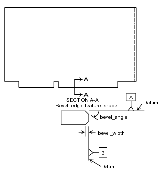
A Bevel_edge_feature_shape_model is a type of
Edge_shape_model
that describes a bevelled edge of a feature with a two-dimensional shape.
EXAMPLE
Figure 1
illustrates a detail of a fabrication drawing that presents some of the information provided by Bevel_edge_feature_shape_model.
The figure illustrates the measurement conditions (including orientation) for generic width and angle attributes.
Figure 1 — Bevel_edge_feature_shape_model
EXPRESS specification:
            *)

            ENTITY Bevel_edge_feature_shape_model

              SUBTYPE OF (Edge_shape_model);


              bevel_width : Length_tolerance_characteristic;


              bevel_angle : Tolerance_characteristic;
WHERE

              WR1: ('CHARACTERISTIC_ARM.STATISTICAL_TOLERANCE_CHARACTERISTIC' IN TYPEOF(bevel_angle)) OR
            ('CHARACTERISTIC_ARM.SYMMETRICAL_TOLERANCE_CHARACTERISTIC' IN TYPEOF(bevel_angle)) OR
            (SIZEOF(QUERY(it <* bevel_angle\Representation.items |
            NOT('VALUE_WITH_UNIT_EXTENSION_ARM.ANGLE_DATA_ELEMENT' IN TYPEOF(bevel_angle\Representation.items))
            )) = 0);

              WR2: NOT('CHARACTERISTIC_ARM.SYMMETRICAL_TOLERANCE_CHARACTERISTIC' IN TYPEOF(bevel_angle)) OR
            (SIZEOF(QUERY(it <* bevel_angle\Representation.items |
            ('VALUE_WITH_UNIT_EXTENSION_ARM.ANGLE_DATA_ELEMENT' IN TYPEOF(bevel_angle\Representation.items))
            )) = 1);

            END_ENTITY;
(*
Attribute definitions:
bevel_width:
specifies the positive value of the
Length_tolerance_characteristic
that is the width of the bevel relative to the edge surface
that is beveled for the Bevel_edge_feature_shape_model.
bevel_angle:
specifies the positive value of an Tolerance_characteristic
measured in the plane of the Shape_definition_3d_plane_projection
relative to the edge surface being beveled. The angle shall be more than 0 and less than 90 degrees when measured from the
applied
surface in the supertype in the direction of edge.
Formal propositions:
WR1:
The bevel_angle shall be of type Statistical_tolerance_characteristic
or of type Symmetrical_tolerance_characteristic, or
all members of its items
shall be of type Angle_data_element.
WR2:
If bevel_angle is of type Symmetrical_tolerance_characteristic,
then there shall be only one instance of Angle_data_element
in its items.
An Edge_shape_model is a type of
Planar_shape_model.
An Edge_shape_model is one of a
Bevel_edge_feature_shape_model,
or a
Radius_edge_feature_shape_model,
or a
Step_edge_feature_shape_model.
Edge_shape_model is provied to describe parametric data necessary to fabricate commonly
used shapes on segments of interconnect substrates.
Edge_shape_model applies to the entire arc length of the feature that is referencing it.
EXPRESS specification:
            *)

            ENTITY Edge_shape_model

              ABSTRACT SUPERTYPE

            OF (ONEOF (Bevel_edge_feature_shape_model,
                                Step_edge_feature_shape_model,
                                Radius_edge_feature_shape_model))

              SUBTYPE OF (Planar_shape_model);


              applied_surface : board_side;
WHERE

              WR1: SIZEOF(QUERY(escss <* USEDIN(SELF,
            'LAYERED_3D_SHAPE_ARM.SHAPE_DEFINITION_3D_INTERSECTION.SURFACE_INTERSECTION_RESULT') | NOT ('PART_TEMPLATE_3D_SHAPE_ARM.EDGE_SEGMENT_CROSS_SECTION'
            IN TYPEOF(escss)))) = 0;

              WR2: NOT EXISTS(SELF\Representation.name);

            END_ENTITY;
(*
Attribute definitions:
applied_surface:
specifies the
board_side
for the Edge_shape_model.
Formal propositions:
WR1:
Edge_shape_model shall be
surface_intersection_result
only for
Edge_segment_cross_section.
WR2:
The
name
shall not be populated.
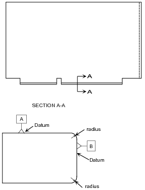
A Radius_edge_feature_shape_model is a type of
Edge_shape_model
that
describes a circular cross sectioned edge. See
Bevel_edge_feature_shape_model
for the additional required geometric information that shall be provided.
EXAMPLE
Figure 2
illustrates the shape related information exchanged with this Application object.
Figure 2 — Radius_edge_feature_shape_model
EXPRESS specification:
            *)

            ENTITY Radius_edge_feature_shape_model

              SUBTYPE OF (Edge_shape_model);


              radius_length : Length_tolerance_characteristic;

            END_ENTITY;
(*
Attribute definitions:
radius_length:
specifies the
Length_tolerance_characteristic
of the radius of the circle that is tangent to the edge
surface and to the lateral surface on which the edge surface is a feature for the Radius_edge_feature_shape_model.
The included angle between the points of tangency shall always be 90 degrees.
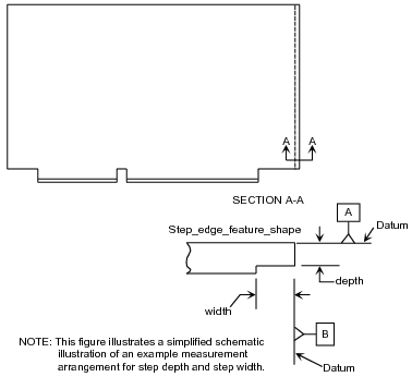
A Step_edge_feature_shape_model is a type of
Edge_shape_model
that is the
two-dimensional definition of the construction of a step edge.
EXAMPLE
Figure 3
illustrates a detail of a fabrication drawing that shows some of the information exchanged for construction of a step edge.
Figure 3 — Step_edge_feature_shape_model
EXPRESS specification:
            *)

            ENTITY Step_edge_feature_shape_model

              SUBTYPE OF (Edge_shape_model);


              step_width : Length_tolerance_characteristic;


              step_depth : Length_tolerance_characteristic;

            END_ENTITY;
(*
Attribute definitions:
step_width:
specifies the
Length_tolerance_characteristic
of the width of the step relative to the edge surface that is stepped.
step_depth:
specifies the Length_tolerance_characteristic
of the depth of the step relative to the datum surface.
         *)

         END_SCHEMA;  -- Edge_shape_feature_arm
(*
© ISO 2006 — All rights reserved


