|
|
Application module:
Assembly technology |
ISO/TS 10303-1649:2019(E)
© ISO
|
This clause specifies the information requirements for the
Assembly technology
application module. The information requirements are specified as the
Application Reference Model (ARM) of this application module.
NOTE 1 A graphical representation of the information
requirements is given in
Annex C.
NOTE 2 The mapping specification is specified in
5.1. It shows how
the information requirements are met by using common resources and
constructs defined or imported in the MIM schema of this application
module.
This clause defines the information requirements to which implementations shall
conform using the EXPRESS language as defined in ISO 10303-11.
The following begins the
Assembly_technology_arm
schema and identifies the necessary external references.
EXPRESS specification:
         *)

            SCHEMA Assembly_technology_arm;
(*
The following EXPRESS interface statements specify the elements
imported from the ARMs of other application modules.
EXPRESS specification:
*)

            USE FROM
            Feature_and_connection_zone_arm;
               --
            ISO/TS 10303-1671
            USE FROM
            Generic_material_aspects_arm;
               --
            ISO/TS 10303-1681
            USE FROM
            Physical_component_feature_arm;
               --
            ISO/TS 10303-1721
            USE FROM
            Product_view_definition_reference_arm;
               --
            ISO/TS 10303-1823
            USE FROM
            Requirement_assignment_arm;
               --
            ISO/TS 10303-1233
(*
NOTE 1
The schemas referenced above are specified in the following
part of ISO 10303:
| Feature_and_connection_zone_arm |
ISO/TS 10303-1671 |
| Generic_material_aspects_arm |
ISO/TS 10303-1681 |
| Physical_component_feature_arm |
ISO/TS 10303-1721 |
| Product_view_definition_reference_arm |
ISO/TS 10303-1823 |
| Requirement_assignment_arm |
ISO/TS 10303-1233 |
NOTE 2
See Annex C,
Figures
C.1and C.2
for a graphical representation of this schema.
This subclause specifies the ARM types
for this application module. The ARM types and
definitions are specified below.
The at_external_identification_item type is an extension
of the
external_identification_item type.
It adds the data
type
Assembly_bond_definition
to the list of alternate data types.
EXPRESS specification:
            *)

            TYPE
            at_external_identification_item =


            SELECT
            BASED_ON
            external_identification_item
            WITH


               (Assembly_bond_definition);

            END_TYPE;

            (*
The at_material_item_select type is an extension
of the
material_item_select type.
It adds the data
type
Assembly_bond_definition
to the list of alternate data types.
EXPRESS specification:
            *)

            TYPE
            at_material_item_select =


            SELECT
            BASED_ON
            material_item_select
            WITH


               (Assembly_bond_definition);

            END_TYPE;

            (*
The at_property_assignment_select type is an extension
of the
property_assignment_select type.
It adds the data
type
Assembly_bond_definition
to the list of alternate data types.
EXPRESS specification:
            *)

            TYPE
            at_property_assignment_select =


            SELECT
            BASED_ON
            property_assignment_select
            WITH


               (Assembly_bond_definition);

            END_TYPE;

            (*
The at_requirement_assignment_item type is an extension
of the
requirement_assignment_item type.
It adds the data
type
Assembly_joint
to the list of alternate data types.
EXPRESS specification:
            *)

            TYPE
            at_requirement_assignment_item =


            SELECT
            BASED_ON
            requirement_assignment_item
            WITH


               (Assembly_joint);

            END_TYPE;

            (*
The bond_feature type is an
extensible list of alternate data types
that allows for the designation of the data
type General_part_feature.
NOTE
The list of entity data types may be
extended in application modules that use the constructs of
this module.
EXPRESS specification:
            *)

            TYPE
            bond_feature =

            EXTENSIBLE

            GENERIC_ENTITY


            SELECT

               (General_part_feature);

            END_TYPE;

            (*
A degree_of_freedom lists the valid qualifiers of a degree of freedom.
EXPRESS specification:
            *)

            TYPE
            degree_of_freedom =

            ENUMERATION

            OF


            (x,
    y,
    z,
    u,
    v,
    w);

            END_TYPE;

            (*
Enumerated item definitions:
x:
specifies component x of a degree of freedom;
y:
specifies component y of a degree of freedom;
z:
specifies component z of a degree of freedom;
u:
specifies component u of a degree of freedom;
v:
specifies component v of a degree of freedom;
w:
specifies component w of a degree of freedom;
This subclause specifies the ARM entities for this
module. Each ARM application entity is an atomic element that
embodies a unique application concept and contains attributes
specifying the data elements of the entity. The ARM
entities and definitions are specified below.
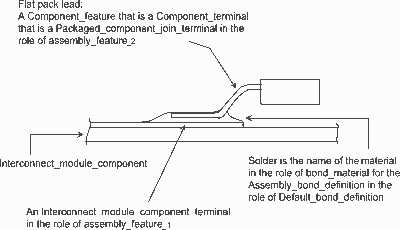
An Assembled_with_bonding is a type of Assembly_joint
that establishes the joint by bonding. Bonding requires the use of material that may change state during the bonding process
to form a permanent or semi-permanent joint. In this context, a permanent or semi-permanent joint means that repair of the
affected part of the assembly would require destruction and replacement of the bond material.
NOTE
The Assembled_with_bonding object relates two assembly features that are
bonded and the Assembly_bond_definition that specifies the category of the
bond, its shape, and its material.
EXAMPLE
Figure 1 illustrates the concept of the joint category described herein and the roles of the related application objects.
Figure 1 — Assembled_with_bonding
EXPRESS specification:
            *)

            ENTITY Assembled_with_bonding

              SUBTYPE OF (Assembly_joint);


              default_bond_definition : Assembly_bond_definition;

            END_ENTITY;
(*
Attribute definitions:
default_bond_definition:
specifies the Assembly_bond_definition used by the Assembled_with_bonding process to form a joint.
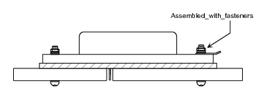
An Assembled_with_fasteners is a type of Assembly_joint
that establishes the assembly by using fasteners to mechanically position a component so that its
component mounting features are connected to component mounting features of another component in the
assembly. The fasteners are associated with the base component using a Product_version_relationship.
EXAMPLE
The usual case for this is the mounting hardware associated with a power device mounted to the Interconnect_module_component.
Figure 2 illustrates the concept of the joint category described herein and the roles of the related Application Objects.
Figure 2 — Assembled_with_fasteners
EXPRESS specification:
            *)

            ENTITY Assembled_with_fasteners

              SUBTYPE OF (Assembly_joint);

            END_ENTITY;
(*
An Assembly_bond_definition is the definition of the joint that
uses bulk material to bond together portions of the assembly. The association of features through
Assembly_bond_definition does not guarantee physical realisability of the design.
EXAMPLE 1
A cut-out may be referenced by a member of Assembly_bond_definition. The semantics of that would be that the walls
of the cut-out would participate in the bond. This standard makes no claims about the properties of such a bond.
NOTE 1
This part of ISO 10303 provides the ability to define the typical shape of the bond through the use of
Default_assembly_bond_shape_model.
EXPRESS specification:
            *)

            ENTITY Assembly_bond_definition;


              name : STRING;


              associated_definition : Product_view_definition_reference_with_local_representation;


              bonded_feature_1 :
            OPTIONAL
            bond_feature;


              bonded_feature_2 :
            OPTIONAL
            bond_feature;
INVERSE

              default_shape : SET[0:1] OF Default_assembly_bond_shape_model FOR shape_characterized_definition;

              bond_category : External_source_identification FOR item;

              bond_material : Material_identification FOR items;
UNIQUE

              UR1: name;

              UR2: associated_definition;
WHERE

              WR1: bonded_feature_1 <> bonded_feature_2;

            END_ENTITY;
(*
Attribute definitions:
name:
the words by which the Assembly_bond_definition is known.
associated_definition:
specifies the role of the
Generic_product_view_definition_reference
for the Assembly_bond_definition. The associated_definition is provided to support the identification of the product classification.
bonded_feature_1:
specifies one role of the
bond_feature
for the Assembly_bond_definition. The bonded_feature_1 defines the first
bond_feature
that will be utilized by an
Assembled_with_bonding. The value of this attribute need not be specified.
bonded_feature_2:
specifies one role of the
bond_feature
for the Assembly_bond_definition. The bonded_feature_2 defines the second
bond_feature
that will be utilized by an
Assembled_with_bonding. The value of this attribute need not be specified.
default_shape:
specifies an inverse relationship that specifies that the existence of the Assembly_bond_definition
is dependent on the existence of the
Default_assembly_bond_shape_model
that specifies the Assembly_bond_definition
as its
shape_characterized_definition.
There shall be not more than one
Default_assembly_bond_shape_model
for a particular Assembly_bond_definition.
The value of this attribute need not be specified.
bond_category:
specifies an inverse relationship that specifies that the existence of the Assembly_bond_definition
is dependent on the existence of the
External_item_identification
that specifies the Assembly_bond_definition
as its
item.
NOTE 2
This part of ISO 10303 does not predefine the classification of bonds for assembly.
EXAMPLE 2
Some typical types are wire bond, solder, and conductive adhesive.
bond_material:
specifies an inverse relationship that specifies that the existence of the Assembly_bond_definition
is dependent on the existence of the
Material_identification
that specifies the Assembly_bond_definition
as its
items.
The bond_material may be a composition.
Formal propositions:
UR1:
The name shall be unique within a population of Assembly_bond_definitions.
UR2:
The associated_definition shall be unique within a population of Assembly_bond_definitions.
WR1:
The item that is bonded_feature_1 shall not be bonded_feature_2.
An Assembly_joint is a type of
Component_feature_joint.
An Assembly_joint may be an
Assembled_with_bonding
or, additionally, may be an
Assembled_with_fasteners.
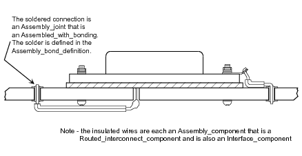
An Assembly_joint is the result of the process that establishes physical connectivity between component features of two
components in an assembly.
EXAMPLE
Figure 3
illustrates the roles assigned to items in an assembly by a designer in constructing a member of Assembly_joint.
Figure 3 — Assembly_joint
NOTE 1
Assembly_joint is a central concept in this part of ISO 10303 that provides information necessary to extract a network description of a
design from the assembly model. Once extracted, the description may be compared to the original requirements.
NOTE 2
Assembly_joint provides critical information necessary to evaluate the appropriateness of the two features related by Assembly_joint to their use in the assembly, given the process used for the joint.
NOTE 3
Assembly_joint provides critical information necessary to evaluate the appropriateness of the relative position of the two features related
by Assembly_joint, given the process used for the joint, and the technology used for each of the associated components, including related tolerances.
NOTE 4
One of these components may be an Interconnect_module_component.
EXPRESS specification:
            *)

            ENTITY Assembly_joint

              SUPERTYPE OF (Assembled_with_fasteners
                ANDOR Assembled_with_bonding)

              SUBTYPE OF (Component_feature_joint);


              SELF\Component_feature_joint.feature_1 RENAMED assembly_feature_1 : Physical_component_feature;


              SELF\Component_feature_joint.feature_2 RENAMED assembly_feature_2 : Physical_component_feature;


              SELF\Component_feature_joint.associated_definition RENAMED associated_assembly : Assembly_definition;
UNIQUE

              UR1: SELF\Shape_element.element_name, associated_assembly;
WHERE

              WR1: assembly_feature_1 :<>: assembly_feature_2;

            END_ENTITY;
(*
Attribute definitions:
assembly_feature_1:
specifies one role of the
Physical_component_feature
for the Assembly_joint.
assembly_feature_2:
specifies one role of the
Physical_component_feature
for the Assembly_joint.
associated_assembly:
specifies the
assembly_module_or_assembly_group_component
that contains the Assembly_joint.
Formal propositions:
UR1:
The combination of
element_name
and associated_assembly
shall be unique within a population of Assembly_joint.
WR1:
A feature shall not be assembled to itself either directly or indirectly.
A Component_mating_constraint_condition is a means to identify the degrees of freedom that have been constrained by a set of members of
Assembly_joint.
A Component_mating_constraint_condition provides "x","y","z" as the set of axes, and "u","v","w" as the set of rotations about those axes.
If an axis is included in the set, then translation along that axis is constrained.
If a rotation is included in the set, then rotation about the corresponding axis is constrained.
The pairs of axis,rotation are: x,u; y,v; z,w.
The axes are referenced in the local coordinate system of the component referenced by the related attribute of the members
of
Assembly_joint referenced by constraining_joints.
Exactly one member of Assembly_component
shall be referenced by the related attribute of members of Assembly_joint
referenced by constraining_joints.
EXPRESS specification:
            *)

            ENTITY Component_mating_constraint_condition;


              name : STRING;


              constraining_joint : SET[1:3] OF Assembly_joint;


              constrained_degree_of_freedom : SET[1:6] OF degree_of_freedom;


              of_context : Part_view_definition;
UNIQUE

              UR1: name, of_context;

            END_ENTITY;
(*
Attribute definitions:
name:
the words by which the Component_mating_constraint_condition is known.
The name specifies the identifier of the Component_mating_constraint_condition in the context of the
Part_design_view.
constraining_joint:
specifies the role of the
Assembly_joint
for the Component_mating_constraint_condition. There shall be at least one Assembly_joint for the
Component_mating_constraint_condition, and there shall be no more than three Assembly_joint for the Component_mating_constraint_condition.
constrained_degree_of_freedom:
specifies the role of the degree_of_freedom for the Component_mating_constraint_condition.
The constrained_degree_of_freedom specifies either 'x', 'y', 'z', 'u', 'v', or 'w' as the identifier of the degrees of freedom
that are constrained for the Component_mating_constraint_condition.
There shall be at least one, and there shall be no more than five members of constrained_degree_of_freedom for the Component_mating_constraint_condition.
of_context:
specifies the role of the
Part_design_view
for the Component_mating_constraint_condition.
Formal propositions:
UR1:
The combination of name and of_context shall be unique within a population of Component_mating_constraint_condition.
A Connection_zone_based_assembly_joint is a type of
Assembly_joint that
provides a finer degree of granularity by specifying the actual connection zones that are involved
in the Assembly_joint.
The connection zones are limited to those explicitly defined in the assembly definition.
NOTE 1
An application plan including this Application Object should be carefully reviewed to ensure available post-processors are
capable of interpreting the information.
NOTE 2
This part of ISO 10303 does not include explicit support for specifying the design instance level of connection zones for
component features in a design
where those component definitions are external to the design. Analysis applications will need to
examine geometric model properties in order to determine which connection zones are incorporated in joints.
EXAMPLE
A component defined in a library may include connection zones in the definition. The relationships between the feature definitions
and the relevant
connection zones will need to be queried in order to
calculate coverage of an assembly joint that includes the feature of the component in the design.
EXPRESS specification:
            *)

            ENTITY Connection_zone_based_assembly_joint

              SUBTYPE OF (Assembly_joint);


              zone_1 : Connection_zone;


              zone_2 : Connection_zone;
WHERE

              WR1: zone_1 :<>: zone_2;

            END_ENTITY;
(*
Attribute definitions:
zone_1:
specifies one role of the
Connection_zone_in_design_view
for the Connection_zone_based_assembly_joint.
zone_2:
specifies one role of the
Connection_zone_in_design_view
for the Connection_zone_based_assembly_joint.
NOTE 3
There are no semantics associated with the sequence of zones in a Connection_zone_based_assembly_joint.
Formal propositions:
WR1:
The zone_1 shall not be zone_2.
A Default_assembly_bond_shape_model is a type of
Geometric_model
that is the shape of an
Assembly_bond_definition.
EXPRESS specification:
            *)

            ENTITY Default_assembly_bond_shape_model

              SUBTYPE OF (Geometric_model);


              shape_characterized_definition : Assembly_bond_definition;
WHERE

              WR1: NOT EXISTS(SELF\Representation.description);

              WR2: SIZEOF(USEDIN(SELF, 'SHAPE_PROPERTY_ASSIGNMENT_ARM.SHAPE_DESCRIPTION_ASSOCIATION.USED_REPRESENTATION'))=0;

            END_ENTITY;
(*
Attribute definitions:
shape_characterized_definition:
specifies the role of the
Assembly_bond_definition
for the Default_assembly_bond_shape_model.
Formal propositions:
WR1:
The
description
shall not be populated.
WR2:
The Default_assembly_bond_shape_model shall not be used in the role of
used_representation
by any Shape_description_association.
         *)

         END_SCHEMA;  -- Assembly_technology_arm
(*
© ISO 2019 — All rights reserved


