| Application interpreted construct: Curve swept solid | ISO 10303-523:2011(E) © ISO |
The part 21 file example below illustrates how this AIC may be used to define the shape of a complex swept solid with full control of the orientation during the sweeping process. This is a section of a part 21 file showing all the relevant geometry and geometric model definitions.
 EXAMPLE 1 /* Part 523 geometry example, sweeping curve is a single segment
Bezier curve */
/* Geometry Definition of area to be swept defined on plane z=0
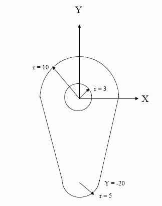
in shape of 2 semi-circles radii 10 and 5 joined by line segments
inner boundary is circle of radius 3 */
#1040 =(LENGTH_UNIT()NAMED_UNIT(*)SI_UNIT(.MILLI.,.METRE.));
#1041 =(NAMED_UNIT(*)PLANE_ANGLE_UNIT()SI_UNIT($,.RADIAN.));
#1100 = CARTESIAN_POINT(’origin’,(0.0,0.0,0.0));
#1101 = DIRECTION(’Dir1’,(1.0,0.0,0.0));
#1103 = DIRECTION(’Dir3’,(0.0,0.0,1.0));
#1104 = DIRECTION(’slope1’,(1.0,4.0,0.0));
#1105 = DIRECTION(’slope2’, (-1.0,4.0,0.0));
/* Points for second arc centre and trimming points */
#1106 = CARTESIAN_POINT(’PtC2’,(0.0,-20.0, 0.0));
#1107 = CARTESIAN_POINT(’PtA’,(10.0, 0.0, 0.0));
#1108 = CARTESIAN_POINT(’PtB’,(-10.0, 0.0, 0.0));
#1109 = CARTESIAN_POINT(’PtE’,(-5.0, -20.0 ,0.0));
#1110 = CARTESIAN_POINT(’PtF’,(5.0, -20.0 ,0.0));
#1111 = CARTESIAN_POINT(’PtG’,(3.0, 0.0 ,0.0));
/* Surface (plane) and curves */
#1120 = AXIS2_PLACEMENT_3D(’Ax2P3DAxes’,#1100,#1103,#1101);
#1121 = PLANE(’Baseplane’, #1120);
#1122 = AXIS2_PLACEMENT_3D(’Ax2P3DCirc2’,#1106,#1103,#1101);
#1124 = CIRCLE(’Circ1’,#1120, 10.0);
#1125 = CIRCLE(’InnerC’,#1120, 3.0);
#1126 = CIRCLE(’Circ2’,#1122, 5.0);
#1127 = VECTOR(’Vec1’,#1104, 10.0);
#1128 = VECTOR(’Vec2’,#1105, 10.0);
#1129 = LINE(’LineFA’,#1110, #1127);
#1130 = LINE(’LineEB’,#1109, #1128);
/* trimmed_curves and surface_curves */
#1140 = TRIMMED_CURVE(’ArcAB’,#1124,(#1107), (#1108),.T.,.CARTESIAN.);
#1141 = TRIMMED_CURVE(’LinBE’,#1130,(#1108), (#1109),.F.,.CARTESIAN.);
#1142 = TRIMMED_CURVE(’ArcEF’,#1126,(#1109), (#1110),.T.,.CARTESIAN.);
#1143 = TRIMMED_CURVE(’LinFA’,#1129,(#1110), (#1107),.T.,.CARTESIAN.);
#1144 = TRIMMED_CURVE(’InC’,#1125,(#1111), (#1111),.F.,.CARTESIAN.);
#1145 = BOUNDED_SURFACE_CURVE(’scAB’,#1140, (#1121), .CURVE_3D.);
#1146 = BOUNDED_SURFACE_CURVE(’scBE’,#1141, (#1121), .CURVE_3D.);
#1147 = BOUNDED_SURFACE_CURVE(’scEF’,#1142, (#1121), .CURVE_3D.);
#1148 = BOUNDED_SURFACE_CURVE(’scFA’,#1143, (#1121), .CURVE_3D.);
#1149 = BOUNDED_SURFACE_CURVE(’scInner’,#1144, (#1121), .CURVE_3D.);
/* segments and composite curves (as boundary_curves) */
/* segAB */
#1155 = COMPOSITE_CURVE_SEGMENT(.CONTINUOUS., .T., #1145);
/* segBE */
#1156 = COMPOSITE_CURVE_SEGMENT(.CONTINUOUS., .T., #1146);
/* segEF */
#1157 = COMPOSITE_CURVE_SEGMENT(.CONTINUOUS., .T., #1147);
/* segFA */
#1158 = COMPOSITE_CURVE_SEGMENT(.CONTINUOUS., .T., #1148);
/* segInner */
#1159 = COMPOSITE_CURVE_SEGMENT(.CONT_SAME_GRADIENT., .T., #1149);
#1160 = OUTER_BOUNDARY_CURVE(’Outer’,(#1155, #1156, #1157, #1158), .F.);
#1161 = BOUNDARY_CURVE(’InnerB’,(#1159), .F.);
/* Area is defined as curve_bounded_surface */
#1170 = CURVE_BOUNDED_SURFACE(’Area’,#1121, (#1160, #1161), .F.);
/* Define points for ruled (Bezier) surface and directrix */
#1181 = CARTESIAN_POINT(’PtP1’,(0.0, 0.0, 10.0));
#1182 = CARTESIAN_POINT(’PtP2’,(60.0, 40.0, 10.0));
#1183 = CARTESIAN_POINT(’PtP3’,(140.0, 60.0, 10.0));
#1184 = CARTESIAN_POINT(’PtP4’,(200.0, 0.0 ,10.0));
/*Points Qn for second side of surface are offset by 100 initially in Y
direction and progressively rotated, final offset in Z direction */
#1191 = CARTESIAN_POINT(’PtQ1’,(0.0, 100.0, 10.0));
#1192 = CARTESIAN_POINT(’PtQ2’,(60.0, 126.0, 60.0));
#1193 = CARTESIAN_POINT(’PtQ3’,(140.0, 110.0, 96.0));
#1194 = CARTESIAN_POINT(’PtQ4’,(200.0, 0.0 ,110.0));
/* Bezier curve and ruled Bezier surface */
#1201 = BEZIER_SURFACE(’RuledSrf’,1 , 3,
((#1181, #1182, #1183, #1184),
(#1191, #1192, #1193, #1194)),
.UNSPECIFIED., .F., .F., .F.);
#1202 = BEZIER_CURVE(’Directrix’, 3,
(#1181, #1182, #1183, #1184), .UNSPECIFIED., .F., .F.);
/* Surface curve and ruled_surface_swept_area_solid */
#1203 = SURFACE_CURVE(’ScDirect’,#1202, (#1201), .CURVE_3D.);
/* swept area is shorter than Bezier curve */
#1204 = RULED_SURFACE_SWEPT_AREA_SOLID(’sweptsol’, #1170, #1203,
0.05, 0.95, #1201);
/* Define swept_disk_solid to fit void of swept area and extend outside */
#1205 = SWEPT_DISK_SOLID(’Core’, #1202, 3.0, $, 0.0, 1.0);
/* Final representation contains swept area and swept disk */
#1290 = (GEOMETRIC_REPRESENTATION_CONTEXT(3)
GLOBAL_UNIT_ASSIGNED_CONTEXT((#1040,#1041))
REPRESENTATION_CONTEXT(’Context for Swept solids’,
’This is a 3D context using millimetres’));
#1300 = CURVE_SWEPT_SOLID_SHAPE_REPRESENTATION(’SweptRep’,
(#1204, #1205), #1290);
NOTE 1 #1204 is a solid formed by sweeping a planar area with a circular hole. The sweeping is along the directrix that is a B-spline curve instanced as a Bezier curve of degree 3 (#1202) this is referenced by surface_curve #1203. The extent of the swept solid is slightly less (0.05 to 0.95) than the parametric extent of the directrix (0.0 to 1.0).
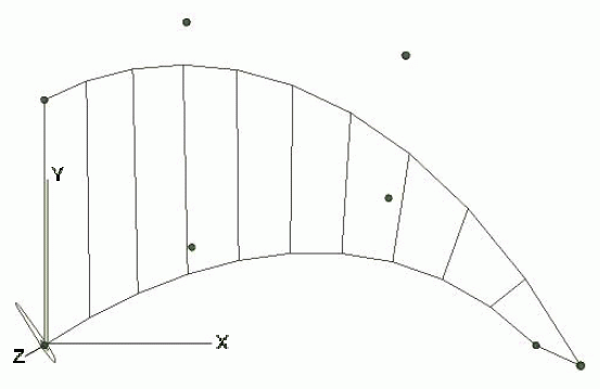
NOTE 2 #1201 defines a ruled surface as a Bezier surface of degree 1 x 3, note that the first sub-list of control points is identical to the control points of curve #1202 which forms one edge of the ruled surface. The directrix could, alternatively, have been defined as the pcurve u = 0. The second sub-list of the control points effectively defines the other edge curve of the ruled surface, in this example they were obtained by translating and progressively rotating the points from the first sub-list to give a final rotation of 90 degrees. The effect is to rotate the area as it is swept along the directrix. The ruled surface, directrix and control points are illustrated in figure E.2.
NOTE 3 The area to be swept is defined by the curve_bounded_surface instance #1170, this lies on the plane z = 0 (#1120) and has an outer boundary (#1160) composed of 2 semi circles of radii 10mm and 5mm joined by straight lines. It also has a circular hole defined by an inner boundary (#1160) which traverses a circle of radius 3mm, centred at the origin, in the negative sense (see #1149, #1144 and #1125). This area is illustrated in figure E.1.
NOTE 4 #1205 is a swept_disk_solid that uses the same directrix as #1204 to sweep a circular disk of radius 3mm (with no inner hole). The parametric extent of the swept disk soild is (0.0 to 1.0) so that it extends beyond the ends of the hole in #1201.
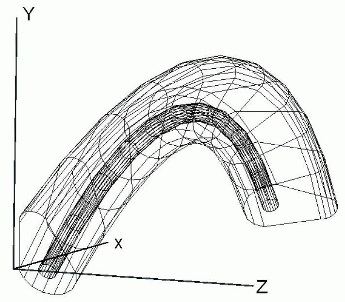
NOTE 5 #1500 is an instance of curve_swept_solid_shape_representation containing the swept solids #1201 and #1205. It is defined in a 3 dimensional geometric_representation_context using millimetres and radians as units. This provides the context for all 3D geometry in the file. The final shape can be interpreted as an insulated cable of complex shape with a twist. #1205 defines a circular wire that exactly fits inside the insulation as defined by #1201. The wire projects slightly at each end. The complete solid is shown in figure E.3.


© ISO 2011 — All rights reserved