|
|
Application module:
Machining features |
ISO/TS 10303-1814:2019(E)
© ISO
|
This clause specifies the information requirements for the
Machining features
application module. The information requirements are specified as the
Application Reference Model (ARM) of this application module.
NOTE 1 A graphical representation of the information
requirements is given in
Annex C.
NOTE 2 The mapping specification is specified in
5.1. It shows how
the information requirements are met by using common resources and
constructs defined or imported in the MIM schema of this application
module.
This clause defines the information requirements to which implementations shall
conform using the EXPRESS language as defined in ISO 10303-11.
The following begins the
Machining_features_arm
schema and identifies the necessary external references.
EXPRESS specification:
         *)

            SCHEMA Machining_features_arm;
(*
The following EXPRESS interface statements specify the elements
imported from the ARMs of other application modules.
EXPRESS specification:
*)

            USE FROM
            Elemental_geometric_shape_arm;
               --
            ISO/TS 10303-1004
            USE FROM
            Feature_and_connection_zone_arm;
               --
            ISO/TS 10303-1671
            USE FROM
            Group_arm;
               --
            ISO/TS 10303-1113
            USE FROM
            Measure_representation_arm;
               --
            ISO/TS 10303-1118
            USE FROM
            Specification_document_arm;
               --
            ISO/TS 10303-1747
            USE FROM
            Value_with_unit_arm;
               --
            ISO/TS 10303-1054
(*
NOTE 1
The schemas referenced above are specified in the following
part of ISO 10303:
| Elemental_geometric_shape_arm |
ISO/TS 10303-1004 |
| Feature_and_connection_zone_arm |
ISO/TS 10303-1671 |
| Group_arm |
ISO/TS 10303-1113 |
| Measure_representation_arm |
ISO/TS 10303-1118 |
| Specification_document_arm |
ISO/TS 10303-1747 |
| Value_with_unit_arm |
ISO/TS 10303-1054 |
NOTE 2
See Annex C,
Figures
C.1, C.2, C.3, C.4, C.5, C.6, C.7, C.8, C.9, C.10, C.11, C.12, C.13, C.14, C.15, C.16, C.17, C.18, C.19and C.20
for a graphical representation of this schema.
This subclause specifies the ARM types
for this application module. The ARM types and
definitions are specified below.
The angle_or_directed_taper type allows for the designation of the data
types
Angle_taper and Directed_taper.
EXPRESS specification:
            *)

            TYPE
            angle_or_directed_taper =


            SELECT

               (Angle_taper,
    Directed_taper);

            END_TYPE;

            (*
The compound_feature_select type allows for the designation of the data
types
Machining_feature and Transition_feature.
EXPRESS specification:
            *)

            TYPE
            compound_feature_select =


            SELECT

               (Machining_feature,
    Transition_feature);

            END_TYPE;

            (*
The end_type_select type allows for the designation of the data
types
Complete_circular_path_feature_component and General_path_feature_component.
EXPRESS specification:
            *)

            TYPE
            end_type_select =


            SELECT

               (Complete_circular_path_feature_component,
    General_path_feature_component);

            END_TYPE;

            (*
The hole_bottom_condition_select type allows for the designation of the data
types
Blind_bottom_condition and Through_bottom_condition.
EXPRESS specification:
            *)

            TYPE
            hole_bottom_condition_select =


            SELECT

               (Blind_bottom_condition,
    Through_bottom_condition);

            END_TYPE;

            (*
The manufacturing_group_select type allows for the designation of the data
types
Manufacturing_feature and Manufacturing_feature_group.
EXPRESS specification:
            *)

            TYPE
            manufacturing_group_select =


            SELECT

               (Manufacturing_feature,
    Manufacturing_feature_group);

            END_TYPE;

            (*
The mf_additional_application_domain_enumeration provides pre-defined identifiers for the additional application domains of
Product_view_definitions.
EXPRESS specification:
            *)

            TYPE
            mf_additional_application_domain_enumeration =

            ENUMERATION

            BASED_ON
            additional_application_domain_enumeration
            WITH


            (machining_feature);

            END_TYPE;

            (*
Enumerated item definitions:
machining_feature:
the application domain is machining features.
The mf_groupable_item type is an extension
of the
groupable_item type.
It adds the data
types
Manufacturing_feature and Manufacturing_feature_group
to the list of alternate data types.
EXPRESS specification:
            *)

            TYPE
            mf_groupable_item =


            SELECT
            BASED_ON
            groupable_item
            WITH


               (Manufacturing_feature,
    Manufacturing_feature_group);

            END_TYPE;

            (*
The pocket_bottom_condition_select type allows for the designation of the data
types
Pocket_bottom_condition and Through_pocket_bottom_condition.
EXPRESS specification:
            *)

            TYPE
            pocket_bottom_condition_select =


            SELECT

               (Pocket_bottom_condition,
    Through_pocket_bottom_condition);

            END_TYPE;

            (*
The profile_select type allows for the designation of the data
types
Profile_floor and Through_profile_floor.
EXPRESS specification:
            *)

            TYPE
            profile_select =


            SELECT

               (Profile_floor,
    Through_profile_floor);

            END_TYPE;

            (*
The replicate_base_select type allows for the designation of the data
types
Machining_feature and Replicate_feature.
EXPRESS specification:
            *)

            TYPE
            replicate_base_select =


            SELECT

               (Machining_feature,
    Replicate_feature);

            END_TYPE;

            (*
The taper_select type allows for the designation of the data
types
Angle_taper, Diameter_taper, and Directed_taper.
EXPRESS specification:
            *)

            TYPE
            taper_select =


            SELECT

               (Angle_taper,
    Diameter_taper,
    Directed_taper);

            END_TYPE;

            (*
The thread_hand provides pre-defined identifiers for left- and right-handed threads.
EXPRESS specification:
            *)

            TYPE
            thread_hand =

            ENUMERATION

            OF


            (left,
    right);

            END_TYPE;

            (*
Enumerated item definitions:
left:
the thread is left handed.
right:
the thread is right-handed.
The thread_side provides pre-defined identifiers for internal and external threads.
EXPRESS specification:
            *)

            TYPE
            thread_side =

            ENUMERATION

            OF


            (internal,
    external);

            END_TYPE;

            (*
Enumerated item definitions:
internal:
the thread is formed on the inside of a cylindrical or conical surface.
external:
the thread is formed on the outside of a cylindrical or conical surface.
The volume_select type allows for the designation of the data
types
Protrusion and Boss.
EXPRESS specification:
            *)

            TYPE
            volume_select =


            SELECT

               (Protrusion,
    Boss);

            END_TYPE;

            (*
This subclause specifies the ARM entities for this
module. Each ARM application entity is an atomic element that
embodies a unique application concept and contains attributes
specifying the data elements of the entity. The ARM
entities and definitions are specified below.
An Angle_taper is a constant change in shape of a feature for a part.
The start of the Angle_taper is at the placement of a feature and is applied to the entire feature.
The length of the taper is determined from the feature that is applying the Angle_taper.
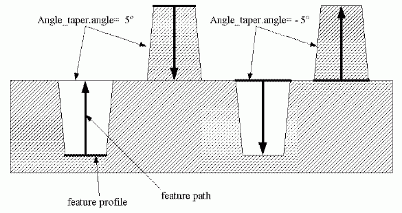
NOTE
Figure 1 illustrates features that have an Angle_taper applied.
Figure 1 — Angle_taper
EXPRESS specification:
            *)

            ENTITY Angle_taper;


              angle : Numerical_item_with_unit;

            END_ENTITY;
(*
Attribute definitions:
angle:
specifies the amount of slope from the start of an Angle_taper to the end of the Angle_taper.
An angle between 0 and 90 degrees or between -90 and -180 degrees indicates that the profile for a
feature grows larger along the feature path.
An angle between 0 and -90 degrees or between 90 and 180
degrees indicates that the profile for a feature grows smaller along the feature path.
A Bevel_gear is a type of
Defined_gear
that is used in meshing pairs where the axes of the pairs intersect.
Each Bevel_gear is either a
Helical_bevel_gear,
or a
Straight_bevel_gear.
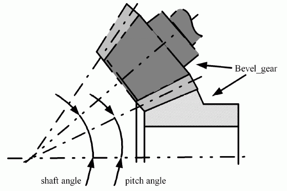
The Bevel_gear definition is based upon the shaft angle which is defined as the smallest angle through which one of the axes must be rotated
to be parallel.
This angle is a critical part of bevel gear design.
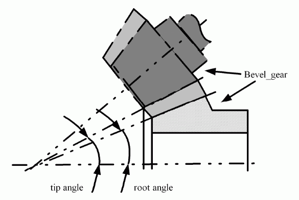
For a gear design, the shaft angle is required for defining the pitch angle from which the tip_angle and root_angle are defined.
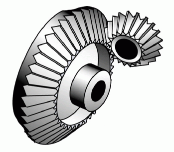
NOTE
Figure 2
illustrates the Bevel_gear, and
Figure 3
illustrates the shaft angle, and pitch angle.
Figure 2 — Bevel_gear
Figure 3 — Bevel_gear with shaft angle, and pitch angle
EXPRESS specification:
            *)

            ENTITY Bevel_gear

              ABSTRACT SUPERTYPE

            OF (ONEOF (Helical_bevel_gear,
                                Straight_bevel_gear))

              SUBTYPE OF (Defined_gear);


              tip_angle : Numerical_item_with_unit;


              root_angle : Numerical_item_with_unit;

            END_ENTITY;
(*
Attribute definitions:
tip_angle:
specifies the angle between the axis and the root of the teeth.
root_angle:
specifies the angle between the axis and the tip of the teeth.
Figure 4 — Bevel_gear with root_angle, and tip_angle
A Blind_bottom_condition is a selection type of
hole_bottom_condition_select
that has material in the bottom of a hole and does not go through the entire part.
Each Blind_bottom_condition is either a
Conical_hole_bottom,
a
Flat_hole_bottom,
a
Flat_with_radius_hole_bottom,
a
Flat_with_taper_hole_bottom,
or a
Spherical_hole_bottom.
EXPRESS specification:
            *)

            ENTITY Blind_bottom_condition

              ABSTRACT SUPERTYPE

            OF (ONEOF (Conical_hole_bottom,
                                Flat_hole_bottom,
                                Flat_with_radius_hole_bottom,
                                Flat_with_taper_hole_bottom,
                                Spherical_hole_bottom));


              start_or_end : BOOLEAN;

            END_ENTITY;
(*
Attribute definitions:
start_or_end:
specifies a Boolean value of TRUE if the Blind_bottom_condition is positioned at the end of a
Round_hole,
and a value of FALSE if it is at the start of the
Round_hole.
A Boss is a type of
Multi_axis_feature
that is a closed shape that protrudes from the surface of the part.
The intersection of the Boss and the base surface may have a radius shaped blend between them.
Each Boss is either a
Circular_boss,
a
General_boss,
or a
Rectangular_boss.
The Boss may be positioned on the face of a part with the Z-axis in the
direction away from the part, or at the top of the Boss with the Z-axis in the direction toward the part face.
EXPRESS specification:
            *)

            ENTITY Boss

              ABSTRACT SUPERTYPE

            OF (ONEOF (Circular_boss,
                                General_boss,
                                Rectangular_boss))

              SUBTYPE OF (Multi_axis_feature);


              boss_height : Linear_path_feature_component;


              fillet_radius :
            OPTIONAL
            Numerical_item_with_unit;


              top_condition : Boss_top_condition;

            END_ENTITY;
(*
Attribute definitions:
boss_height:
specifies the maximum height of a Boss measured from the highest point on the Boss to the farthest point of intersection between the Boss and the part surface.
The placement and orientation of the
Linear_path_feature_component
shall be the same as the Boss feature.
fillet_radius:
specifies a radius shape blend between a Boss and the surrounding surface at the base of the Boss.
The value of this attribute need not be specified.
top_condition:
specifies the shape of the top of a Boss feature.
A Boss_top_condition is the end shape of a
Boss
that is the farthest distance away from the intersection of the face of the part and the
Boss.
A
Boss
top may be either flat or of any other shape.
Each Boss_top_condition is either a
General_top_condition
or a
Planar_top_condition.
EXPRESS specification:
            *)

            ENTITY Boss_top_condition

              ABSTRACT SUPERTYPE

            OF (ONEOF (General_top_condition,
                                Planar_top_condition));


              top_radius :
            OPTIONAL
            Numerical_item_with_unit;


              start_or_end : BOOLEAN;

            END_ENTITY;
(*
Attribute definitions:
top_radius:
specifies a radius shape blend between a Boss_top_condition and the surrounding
Boss
surface at the top of the
Boss.
The value of this attribute need not be specified.
NOTE
If the Boss_top_condition is a
General_top_condition
that defines a spherical shape, the top_radius does not necessarily apply.
start_or_end:
specifies a Boolean value of TRUE if the Boss_top_condition is located at the start of the
Boss,
FALSE if it is located at the end of the
Boss.
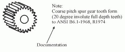
A Catalogue_gear is a type of
Gear
that is a reference to a document containing the information to create a gear on a part.
NOTE
Figure 5
illustrates a Catalogue_gear that is a 24 toothed gear with further definition found in a specification.
Figure 5 — Catalogue_gear
EXPRESS specification:
            *)

            ENTITY Catalogue_gear

              SUBTYPE OF (Gear);


              documentation : Specification_definition;

            END_ENTITY;
(*
Attribute definitions:
documentation:
specifies the document that defines information pertaining to a
Gear
feature.
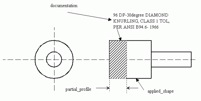
A Catalogue_knurl is a type of
Knurl
that is a reference to a document containing the information to create a knurl on a part.
NOTE
Figure 6
illustrates a Catalogue_knurl that is a diagonal knurl with further definition found in a specification called ANSI B94.6.
Figure 6 — Catalogue_knurl
EXPRESS specification:
            *)

            ENTITY Catalogue_knurl

              SUBTYPE OF (Knurl);


              documentation : Specification_definition;

            END_ENTITY;
(*
Attribute definitions:
documentation:
specifies the document that defines information pertaining to a
Knurl
feature.
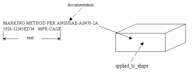
A Catalogue_marking is a type of
Marking_feature
that is a reference to a document containing the information for marking on a surface of a part.
NOTE
Figure 7
illustrates a Catalogue_marking with a
text
value of '1928-12345ED34' a documentation value of 'ANSI/SAEAS478-2 ', and associated data for the
applied_to_shape.
Figure 7 — Catalogue_marking
EXPRESS specification:
            *)

            ENTITY Catalogue_marking

              SUBTYPE OF (Marking_feature);


              documentation : Specification_definition;

            END_ENTITY;
(*
Attribute definitions:
documentation:
specifies the document or specification that defines information pertaining to a
Marking_feature
feature.
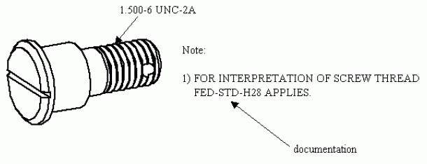
A Catalogue_thread is a type of
Thread
that is a reference to a document containing the information to create threads on a part.
NOTE
Figure 8
illustrates a Catalogue_thread that is an outer thread with values for the documentation associated data.
Figure 8 — Catalogue_thread
EXPRESS specification:
            *)

            ENTITY Catalogue_thread

              SUBTYPE OF (Thread);


              documentation : Specification_definition;


              major_diameter :
            OPTIONAL
            Numerical_item_with_unit;

            END_ENTITY;
(*
Attribute definitions:
documentation:
specifies the document that defines information pertaining to a
Thread
feature.
major_diameter:
specifies the dimension of the largest diameter of the
Thread
and is applied to both an internal and an external thread.
The value of this attribute need not be specified.
A Chamfer is a type of
Transition_feature
that is a transition between corresponding edges of two joining non-coplanar surfaces, having a flat cross section.
A Chamfer feature requires an offset length from one face, and either an angular amount from the same surface or an offset length from
a second face.
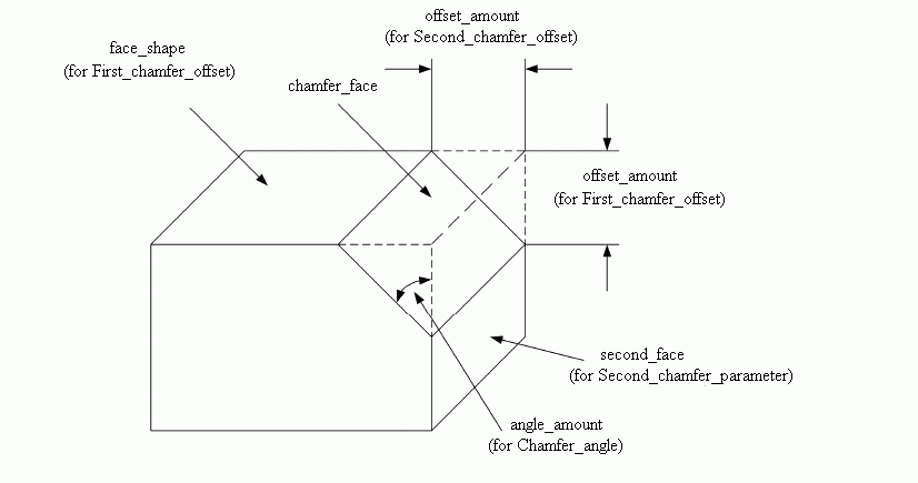
NOTE
Figure 9
illustrates a Chamfer applied to a rectangular block and the chamfer_face associated data.
The offset amount and angle amount attributes apply to the
First_chamfer_offset,
Second_chamfer_offset,
Second_chamfer_parameter,
and
Chamfer_angle
entities.
Figure 9 — Chamfer
EXPRESS specification:
            *)

            ENTITY Chamfer

              SUBTYPE OF (Transition_feature);


              chamfer_face : Face_shape_element;


              first_parameter : First_chamfer_offset;


              second_parameter : Second_chamfer_parameter;

            END_ENTITY;
(*
Attribute definitions:
chamfer_face:
specifies the flat transition face between the two edges of two faces.
first_parameter:
specifies a face and offset amount for one of the edges of the Chamfer.
second_parameter:
specifies a face and either an offset amount or angle amount for one of the edges of the Chamfer.
A Chamfer_angle is a type of
Second_chamfer_parameter
that is the measured angle from the
Second_chamfer_offset
face to the
Chamfer
face for creating a
Chamfer
feature.
NOTE
Figure 9
illustrates a
Chamfer,
a
Chamfer_angle, and the angle_amount associated data.
EXPRESS specification:
            *)

            ENTITY Chamfer_angle

              SUBTYPE OF (Second_chamfer_parameter);


              angle_amount : Numerical_item_with_unit;

            END_ENTITY;
(*
Attribute definitions:
angle_amount:
specifies the angular measurement from a face for creating a
Chamfer
feature.
A Circular_boss is a type of
Boss
that is a cylindrical shape.
A Circular_boss may be tapered.
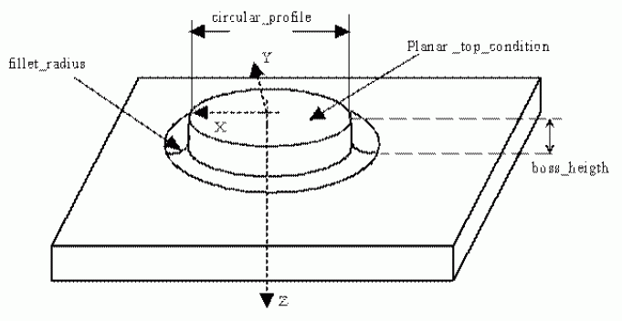
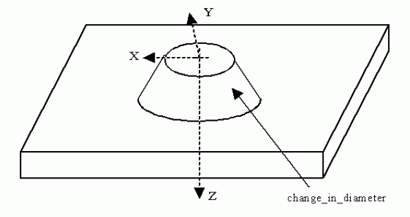
NOTE
Figure 10
illustrates a Circular_boss with a planar top and a fillet radius, and
Figure 11
illustrates a Circular_boss with taper.
Figure 10 — Circular_boss
Figure 11 — Circular_boss with taper
EXPRESS specification:
            *)

            ENTITY Circular_boss

              SUBTYPE OF (Boss);


              circular_profile : Circular_closed_profile;


              change_in_diameter :
            OPTIONAL
            taper_select;

            END_ENTITY;
(*
Attribute definitions:
circular_profile:
specifies the diameter required by a Circular_boss.
The diameter is the distance across the Circular_boss.
The placement of the circular_profile shall be with the origin of the
Circular_closed_profile
at the origin of the Circular_boss.
The X-axis and Y-axis of the profile shall be the same as the X-axis and Y-axis of the Circular_boss.
change_in_diameter:
specifies a taper that defines the change in shape of the Circular_boss.
The value of this attribute need not be specified.
A Circular_closed_profile is a type of
Closed_profile
that is an enclosed area bounded by a circle.
The orientation is at the centre of the circle.
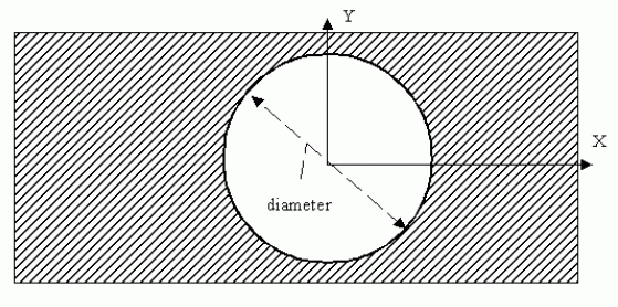
NOTE
Figure 12
illustrates a Circular_closed_profile.
Figure 12 — Circular_closed_profile
EXPRESS specification:
            *)

            ENTITY Circular_closed_profile

              SUBTYPE OF (Closed_profile);


              diameter : Numerical_item_with_unit;

            END_ENTITY;
(*
Attribute definitions:
diameter:
specifies the distance across the Circular_closed_profile.
A Circular_closed_shape_profile is a type of
Shape_profile
that defines a completely enclosed volume.
EXPRESS specification:
            *)

            ENTITY Circular_closed_shape_profile

              SUBTYPE OF (Shape_profile);


              closed_boundary : Circular_closed_profile;

            END_ENTITY;
(*
Attribute definitions:
closed_boundary:
specifies the outline of the
Shape_profile
feature.
The outline defines an area that shall be enclosed and circular.
The placement of the
Closed_profile
shall be with the origin of the
Path_feature_component,
which defines the profile, at the origin of the Circular_closed_shape_profile.
The X-axis and Y-axis of the profile shall be the same as the X-axis and Y-axis of the Circular_closed_shape_profile.
A Circular_cutout is a type of
Cutout_feature
that is an enclosed volume of circular shape.
A Circular_cutout is similar in definition to a
Hole,
but differ in the type of process required to manufacture.
EXPRESS specification:
            *)

            ENTITY Circular_cutout

              SUBTYPE OF (Cutout_feature);


              circular_boundary : Circular_closed_profile;

            END_ENTITY;
(*
Attribute definitions:
circular_boundary:
specifies the distance across the Circular_cutout.
The placement and orientation of the
Circular_closed_profile
shall be the same as the Circular_cutout feature.
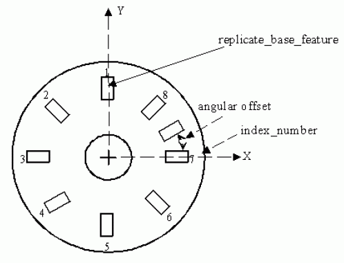
A Circular_offset_pattern is a
Circular_pattern
with a modification of the placement of an occurrence of the base feature relative to its expected placement.
NOTE
Figure 13
illustrates a Circular_offset_pattern. The rectangular base shape is offset from index number seven.
Figure 13 — Circular_offset_pattern
EXPRESS specification:
            *)

            ENTITY Circular_offset_pattern;


              index_number : INTEGER;


              angular_offset : Numerical_item_with_unit;
INVERSE

              relocated_base_feature_for : SET[1:?] OF Circular_pattern FOR relocated_base_feature;

            END_ENTITY;
(*
Attribute definitions:
index_number:
specifies the value for unique identification of a location of a base feature used in a
Circular_pattern.
angular_offset:
specifies the amount of offset from the expected feature location in a
Circular_pattern,
along the base feature diameter for placing another feature.
relocated_base_feature_for:
an inverse relationship that specifies that the existence of the Circular_offset_pattern is dependent on the existence of the
Circular_pattern
that specifies the Circular_offset_pattern as its
relocated_base_feature.
There shall exist one or more
Circular_patterns
for the Circular_offset_pattern.
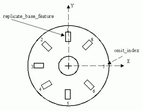
A Circular_omit_pattern is a
Circular_pattern
with an omission of an occurrence of the base feature.
NOTE
Figure 14
illustrates a Circular_omit_pattern with the omission of the rectangular base shape from index number 7.
Figure 14 — Circular_omit_pattern
EXPRESS specification:
            *)

            ENTITY Circular_omit_pattern;


              omit_index : INTEGER;
INVERSE

              missing_base_feature_for : SET[1:?] OF Circular_pattern FOR missing_base_feature;

            END_ENTITY;
(*
Attribute definitions:
omit_index:
specifies the value for unique identification of the base feature to be omitted in a
Circular_pattern.
missing_base_feature_for:
an inverse relationship that specifies that the existence of the Circular_omit_pattern is dependent on the existence of the
Circular_pattern
that specifies the Circular_omit_pattern as its
missing_base_feature.
There shall exist one or more
Circular_patterns
for the Circular_omit_pattern.
A Circular_path_feature_component is a type of
Path_feature_component
that is a direction of travel along an arc of constant radius around the Z-axis of the feature.
Each Circular_path_feature_component is either a
Complete_circular_path_feature_component
or a
Partial_circular_path_feature_component.
EXPRESS specification:
            *)

            ENTITY Circular_path_feature_component

              ABSTRACT SUPERTYPE

            OF (ONEOF (Complete_circular_path_feature_component,
                                Partial_circular_path_feature_component))

              SUBTYPE OF (Path_feature_component);


              radius : length_measure;

            END_ENTITY;
(*
Attribute definitions:
radius:
specifies the constant distance from an axis for the Circular_path_feature_component.
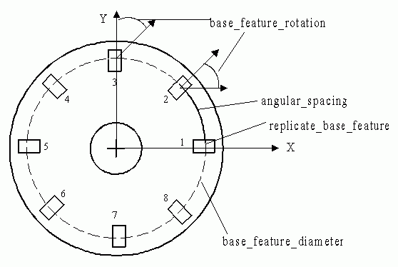
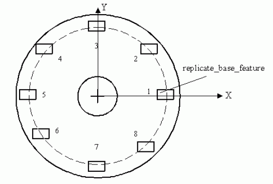
A Circular_pattern is a type of
Replicate_feature
that is a base feature arranged in a pattern around a circular arc, equally spaced about an axis.
Instances of base features need not be rotated.
When a base feature rotation is required, the first feature instance is not rotated.
The second through the Nth feature instance are rotated by the same angular amount measured from the placement and orientation
of
the preceding feature instance. (This does not imply the use of chain dimensioning.)
NOTE
Figure 15
illustrates a Circular_pattern with rotation of a base feature, and
Figure 16
illustrates a Circular_pattern without rotation.
Figure 15 — Circular_pattern with rotation
Figure 16 — Circular_pattern without rotation
EXPRESS specification:
            *)

            ENTITY Circular_pattern

              SUBTYPE OF (Replicate_feature);


              relocated_base_feature : SET[0:?] OF Circular_offset_pattern;


              missing_base_feature : SET[0:?] OF Circular_omit_pattern;


              base_feature_rotation : Numerical_item_with_unit;


              number_of_features : INTEGER;


              base_feature_diameter :
            OPTIONAL
            Numerical_item_with_unit;


              angular_spacing : Numerical_item_with_unit;

            END_ENTITY;
(*
Attribute definitions:
relocated_base_feature:
specifies the definition to offset any number of base features from the
Circular_pattern.
The relocated_base_feature need not be specified for a
Circular_pattern.
There may be more than one relocated_base_feature for a
Circular_pattern.
missing_base_feature:
specifies the definition to remove any number of base features from the
Circular_pattern.
The missing_base_feature need not be specified for a
Circular_pattern.
There may be more than one missing_base_feature for a
Circular_pattern.
base_feature_rotation:
specifies the angle to rotate one feature regarding to the orientation of a previous feature in a
Circular_pattern.
number_of_features:
specifies the quantity of a base feature to be used in a
Circular_pattern.
base_feature_diameter:
specifies the size of the circle for placement of features in a
Circular_pattern.
The value of this attribute need not be specified.
angular_spacing:
specifies the angle amount between features in a
Circular_pattern.
A Closed_profile is a type of
Profile
that is an outline or shape that bounds an enclosed area with no opening.
Each Closed_profile is either a
Circular_closed_profile,
a
General_closed_profile,
an
Ngon_profile,
or a
Rectangular_closed_profile.
EXPRESS specification:
            *)

            ENTITY Closed_profile

              ABSTRACT SUPERTYPE

            OF (ONEOF (Circular_closed_profile,
                                General_closed_profile,
                                Ngon_profile,
                                Rectangular_closed_profile))

              SUBTYPE OF (Profile);

            END_ENTITY;
(*
A Closed_slot is a type of
Slot
that has a course of travel defined by a
Path_feature_component
that is closed and has no opening.
EXPRESS specification:
            *)

            ENTITY Closed_slot

              SUBTYPE OF (Slot);


              end_condition : Loop_slot_end_type;


              course_of_travel : end_type_select;

            END_ENTITY;
(*
Attribute definitions:
end_condition:
specifies the type of closed shape at the ends of the
Slot.
course_of_travel:
specifies a 3D space curve, that when combine with a
Profile,
creates the shape of the
Slot.
A Complete_circular_path_feature_component is a type of
Circular_path_feature_component
that is a direction of travel that begins and ends at the same point on the arc.
NOTE
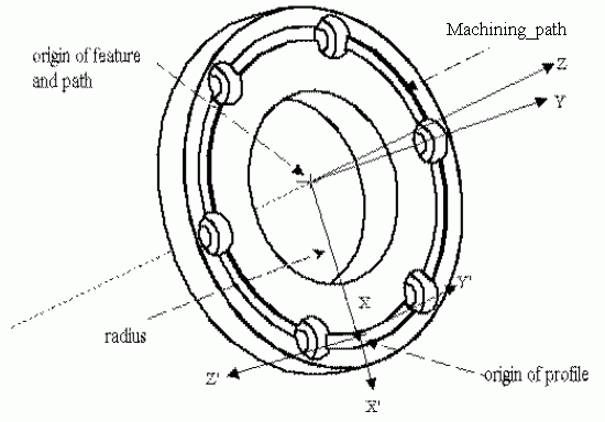
Figure 17
illustrates a
Slot
feature with a
Square_u_profile
and a Complete_circular_path_feature_component.
Figure 17 — Complete_circular_path_feature_component
EXPRESS specification:
            *)

            ENTITY Complete_circular_path_feature_component

              SUBTYPE OF (Circular_path_feature_component);

            END_ENTITY;
(*
A Compound_feature is a type of
Machining_feature
that is a union of one or more
Machining_feature
objects to create a more complex feature definition.
The placement of a Compound_feature is relative to either the part, another Compound_feature, or a
Replicate_feature
which uses a Compound_feature as the base feature.
Features which are elements of the Compound_feature have placement defined relative to the Compound_feature placement.
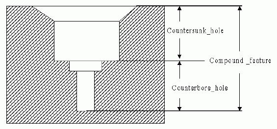
NOTE
Figure 18
illustrates an example of a Compound_feature with one
Counterbore_hole
feature and one
Countersunk_hole
feature.
Figure 18 — Compound_feature
EXPRESS specification:
            *)

            ENTITY Compound_feature

              SUBTYPE OF (Machining_feature);


              element : SET[2:?] OF Compound_feature_element;

            END_ENTITY;
(*
Attribute definitions:
element:
specifies the base features that when combined defines a Compound_feature.
There shall be more than one element for a Compound_feature.
A Compound_feature_element is a specification of the type of
Machining_feature
or
Transition_feature
to be used for an element of a
Compound_feature.
A
Compound_feature
consists of two or more Compound_feature_element objects and need not require Compound_feature_element objects to be ordered.
EXPRESS specification:
            *)

            ENTITY Compound_feature_element;


              element : compound_feature_select;

            END_ENTITY;
(*
Attribute definitions:
element:
specifies the base feature to be used as one of the components for the
Compound_feature.
A Compound_feature_relationship is a definition of the sequence in which the
Compound_feature
elements are applied in the
Compound_feature.
The Compound_feature_relationship defines which feature is the preceding feature and which is the succeeding feature.
EXPRESS specification:
            *)

            ENTITY Compound_feature_relationship;


              predecessor : Compound_feature_element;


              successor : Compound_feature_element;

            END_ENTITY;
(*
Attribute definitions:
predecessor:
specifies the
Compound_feature_element
with the highest precedence.
successor:
specifies
Compound_feature_element
with a lesser precedence.
A Conical_hole_bottom is a type of
Blind_bottom_condition
that defines the bottom of a
Round_hole
to be conical in shape.
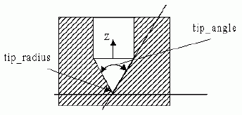
A Conical_hole_bottom shall be a constant decrease in the hole diameter until the radius is zero.
The Conical_hole_bottom may have a tip_radius defined at the smallest end of the Conical_hole_bottom.
NOTE
Figure 19
illustrates the Conical_hole_bottom for a
Round_hole.
Figure 19 — Conical_hole_bottom
EXPRESS specification:
            *)

            ENTITY Conical_hole_bottom

              SUBTYPE OF (Blind_bottom_condition);


              tip_angle : Numerical_item_with_unit;


              tip_radius :
            OPTIONAL
            Numerical_item_with_unit;

            END_ENTITY;
(*
Attribute definitions:
tip_angle:
specifies the amount of constant slope to decrease the
Round_hole
diameter until the diameter is zero.
The tip_angle is a conical bottom for a
Round_hole.
The tip_angle shall be greater than 0 degrees and less than 180 degrees.
tip_radius:
specifies the radius of a conical bottom for a
Round_hole.
A conical bottom is a constant decrease in diameter until the diameter is zero, or until it becomes tangent to a tip_radius.
The value of this attribute need not be specified.
A Constant_radius_edge_round is a type of
Edge_round
that is defined with a constant radius value.
NOTE
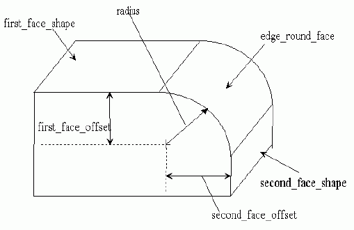
Figure 20
illustrates the Constant_radius_edge_round on a rectangular block.
Figure 20 — Constant_radius_edge_round
EXPRESS specification:
            *)

            ENTITY Constant_radius_edge_round

              SUBTYPE OF (Edge_round);


              first_face_offset :
            OPTIONAL
            Numerical_item_with_unit;


              second_face_offset :
            OPTIONAL
            Numerical_item_with_unit;


              radius : Numerical_item_with_unit;

            END_ENTITY;
(*
Attribute definitions:
first_face_offset:
specifies the amount of offset from the
first_face_shape
to the centre of the
edge_round_face.
The value of this attribute need not be specified.
second_face_offset:
specifies the amount of offset from the
second_face_shape
to the centre of the
edge_round_face.
The value of this attribute need not be specified.
radius:
specifies the amount of curvature for a convex transition between the two faces of a Constant_radius_edge_round.
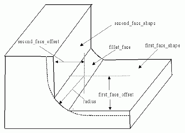
A Constant_radius_fillet is a type of
Fillet
that is defined with a constant radius value.
NOTE
Figure 21
illustrates the Constant_radius_fillet.
The
Fillet
surface is not necessarily tangent to the other surfaces because the offsets.
Figure 21 — Constant_radius_fillet
EXPRESS specification:
            *)

            ENTITY Constant_radius_fillet

              SUBTYPE OF (Fillet);


              first_face_offset :
            OPTIONAL
            Numerical_item_with_unit;


              second_face_offset :
            OPTIONAL
            Numerical_item_with_unit;


              radius : Numerical_item_with_unit;

            END_ENTITY;
(*
Attribute definitions:
first_face_offset:
specifies the amount of offset from the
first_face_shape
to the centre of the
fillet_face.
The value of this attribute need not be specified.
second_face_offset:
specifies the amount of offset from the
second_face_shape
to the centre of the
fillet_face.
The value of this attribute need not be specified.
radius:
specifies the amount of curvature for a concave transition between two surfaces.
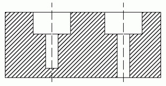
A Counterbore_hole is a type of
Hole
that is a combination of two
Round_holes.
The first
Round_hole
shall have either a
Through_bottom_condition
or
Blind_bottom_condition,
the second shall have a
Blind_bottom_condition,
and a larger diameter than the first
Round_hole.
The top of the first
Round_hole
shall mate with the bottom of the second
Round_hole.
The Counterbore_hole orientation shall be the same as the orientation of the first
Round_hole.
Both
Round_holes
shall be co-axial.
NOTE
Figure 22
illustrates the Counterbore_hole with a
Blind_bottom_condition
and a
Through_bottom_condition.
Figure 22 — Counterbore_hole
EXPRESS specification:
            *)

            ENTITY Counterbore_hole

              SUBTYPE OF (Hole);


              smaller_hole : Round_hole;


              larger_hole : Round_hole;
WHERE

              WR1: SIZEOF(['MACHINING_FEATURES_ARM.COUNTERSUNK_HOLE',
            'MACHINING_FEATURES_ARM.ROUND_HOLE'] * TYPEOF(SELF)) = 0;

            END_ENTITY;
(*
Attribute definitions:
smaller_hole:
specifies the
Round_hole
that will be used as the smaller hole for the Counterbore_hole.
larger_hole:
specifies the
Round_hole
that will be used as the larger hole for the Counterbore_hole.
Formal propositions:
WR1:
A Counterbore_hole shall not also be a
Countersunk_hole
nor shall it be a
Round_hole.
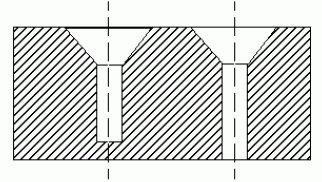
A Countersunk_hole is a type of
Hole
that is a combination of two
Round_holes.
The first
Round_hole
shall have a
Through_bottom_condition
or
Blind_bottom_condition.
The second shall be a
Round_hole
with a
Blind_bottom_condition,
and a taper.
The top of the first
Round_hole
shall mate with the bottom of the second
Round_hole.
The taper of the second
Round_hole
shall be larger than the diameter of the
Round_hole,
decreasing to the same diameter at the point where the two holes join.
The Countersunk_hole orientation shall be the same as the orientation of the first
Round_hole.
Both
Round_holes
shall be co-axial.
NOTE
Figure 23
illustrates the Countersunk_hole with a
Blind_bottom_condition
and a
Through_bottom_condition.
Figure 23 — Countersunk_hole
EXPRESS specification:
            *)

            ENTITY Countersunk_hole

              SUBTYPE OF (Hole);


              constant_diameter_hole : Round_hole;


              tapered_hole : Round_hole;
WHERE

              WR1: SIZEOF(['MACHINING_FEATURES_ARM.COUNTERBORE_HOLE',
            'MACHINING_FEATURES_ARM.ROUND_HOLE'] * TYPEOF(SELF)) = 0;

            END_ENTITY;
(*
Attribute definitions:
constant_diameter_hole:
specifies the
Round_hole
without a taper that will be used as the constant diameter hole for the Countersunk_hole.
tapered_hole:
specifies the
Round_hole
with a taper that will be used as the tapered hole for the Countersunk_hole.
Formal propositions:
WR1:
A Countersunk_hole shall not also be a
Counterbore_hole
nor shall it be a
Round_hole.
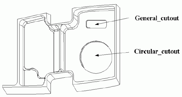
A Cutout_feature is a type of
Pocket
that is a volume to be removed from the part.
Cutouts shall pass through two faces of a part.
Each Cutout_feature is either a
Circular_cutout
or a
General_cutout.
NOTE
Figure 24
illustrates the Cutout_feature.
Figure 24 — Cutout_feature
EXPRESS specification:
            *)

            ENTITY Cutout_feature

              ABSTRACT SUPERTYPE

            OF (ONEOF (Circular_cutout,
                                General_cutout))

              SUBTYPE OF (Pocket);


              SELF\Pocket.bottom_condition : Through_pocket_bottom_condition;

            END_ENTITY;
(*
Attribute definitions:
bottom_condition:
specifies the shape of the bottom of a Cutout_feature feature.
The bottom_condition shall pass entirely through the part, it shall be a
Through_pocket_bottom_condition.
A Defined_gear is a type of
Gear
that is specified explicitly, all attributes for a
Gear
are declared and defined.
Each Defined_gear is either a
Bevel_gear,
a
Helical_gear
or a
Spur_gear.
EXPRESS specification:
            *)

            ENTITY Defined_gear

              ABSTRACT SUPERTYPE

            OF (ONEOF (Bevel_gear,
                                Helical_gear,
                                Spur_gear))

              SUBTYPE OF (Gear);

            END_ENTITY;
(*
A Defined_marking is a type of
Marking_feature
that is specified explicitly, all attributes for a
Marking_feature
are declared and defined.
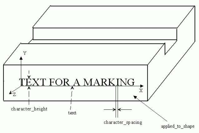
NOTE
Figure 25
illustrates the Defined_marking on a rectangular block shape and with text of 'TEXT FOR A MARKING'.
Figure 25 — Defined_marking
EXPRESS specification:
            *)

            ENTITY Defined_marking

              SUBTYPE OF (Marking_feature);


              font_name :
            OPTIONAL
            text;


              special_instruction :
            OPTIONAL
            text;


              character_spacing :
            OPTIONAL
            Numerical_item_with_unit;


              character_height :
            OPTIONAL
            Numerical_item_with_unit;

            END_ENTITY;
(*
Attribute definitions:
font_name:
specifies the appearance of the characters.
A font consists of type face, treatment, and size.
The value of this attribute need not be specified.
EXAMPLE
Examples of font_name characteristic are type face Times Roman a treatment of Bold or Italic size 10 point.
special_instruction:
specifies a description on how to apply the text given by the Defined_marking entity.
The value of this attribute need not be specified.
character_spacing:
specifies the amount of space between text letters used for a Defined_marking feature.
The value of this attribute need not be specified.
character_height:
specifies the size of the text used for a Defined_marking feature.
The value of this attribute need not be specified.
A Defined_thread is a type of
Thread
that is specified explicitly.
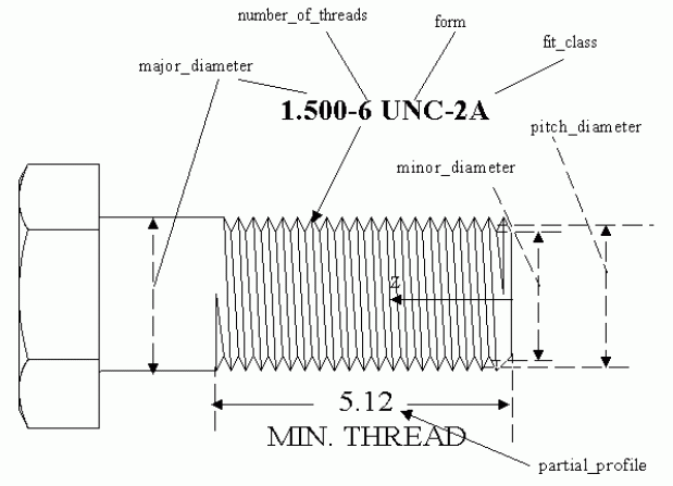
NOTE
Figure 26
illustrates a Defined_thread.
The drawing note '1.500-6 UNC-2A' applies to the thread and is separated into several of the Defined_thread attributes.
Figure 26 — Defined_thread
EXPRESS specification:
            *)

            ENTITY Defined_thread

              SUBTYPE OF (Thread);


              crest :
            OPTIONAL
            Numerical_item_with_unit;


              minor_diameter :
            OPTIONAL
            Numerical_item_with_unit;


              pitch_diameter :
            OPTIONAL
            Numerical_item_with_unit;


              major_diameter : Numerical_item_with_unit;

            END_ENTITY;
(*
Attribute definitions:
crest:
specifies the distance between the opposing points of the thread.
The crest is formed by the intersection of the sides of the thread if extended, if necessary, beyond the top of the thread.
The value of this attribute need not be specified.
minor_diameter:
specifies the dimension of the smallest diameter of the Defined_thread and is applied to both an internal and an external thread.
The value of this attribute need not be specified.
pitch_diameter:
specifies the dimension of an imaginary cylinder passing through the threads to
make equal the widths of the threads and the widths of the spaces cut by the cylinder.
The value of this attribute need not be specified.
major_diameter:
specifies the dimension of the largest diameter of the
Thread
and is applied to both an internal and an external thread.
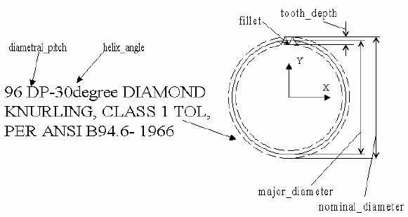
A Diagonal_knurl is a type of
Turned_knurl
with helical cuts at an angle about the axis of a surface.
NOTE
Figure 27
illustrates a Diagonal_knurl with a right-hand helix.
Figure 27 — Diagonal_knurl
EXPRESS specification:
            *)

            ENTITY Diagonal_knurl

              SUBTYPE OF (Turned_knurl);


              helix_hand : text;


              helix_angle : Numerical_item_with_unit;

            END_ENTITY;
(*
Attribute definitions:
helix_hand:
specifies a description of whether the helix angle is applied to an orientation axis in a
clockwise or a counter clockwise direction.
helix_angle:
specifies the angle the knurl pattern makes with the orientation axis of an applied to surface.
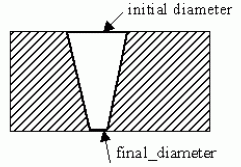
A Diameter_taper is a constant change in shape of a feature for a part.
A Diameter_taper starts at the placement of a feature and is applied to the entire feature.
The initial diameter and the length of the taper is determined from the
Machining_feature
that is applying the Diameter_taper.
The final_diameter is specified as a diameter different than the initial diameter.
NOTE 1
Figure 28
illustrates the Diameter_taper.
Figure 28 — Diameter_taper
EXPRESS specification:
            *)

            ENTITY Diameter_taper;


              final_diameter : Numerical_item_with_unit;

            END_ENTITY;
(*
Attribute definitions:
final_diameter:
specifies the diameter of the circle at the end of the taper.
The final_diameter may be smaller or larger than the beginning diameter for a
Machining_feature.
NOTE 2
The diameter at the beginning of the Diameter_taper is the same as the referencing feature diameter.
A Diamond_knurl is a type of
Turned_knurl
that is a knurl ridge that is doubly helical, a left-hand and a right-hand helix, about the axis of a surface,
with equal spacing of the two.
NOTE
Figure 29
illustrates a Diamond_knurl.
Figure 29 — Diamond_knurl
EXPRESS specification:
            *)

            ENTITY Diamond_knurl

              SUBTYPE OF (Turned_knurl);


              helix_angle : Numerical_item_with_unit;

            END_ENTITY;
(*
Attribute definitions:
helix_angle:
specifies the angle the knurl pattern makes with the orientation axis of an applied to surface.
A Directed_taper is a constant change in shape of a feature for a part.
A Directed_taper starts at the location of the placement of a feature and is applied to the entire feature.
The length of the taper is determined from the
Machining_feature
that is applying the Directed_taper.
EXPRESS specification:
            *)

            ENTITY Directed_taper;


              direction : Direction_element;


              angle : Numerical_item_with_unit;

            END_ENTITY;
(*
Attribute definitions:
direction:
specifies the reference direction from which the Directed_taper angle is measured.
The direction specifies a vector that points in the direction to apply the taper.
angle:
specifies the amount of slope from the start of the Directed_taper to the end of the Directed_taper.
An angle between zero and 90 degrees or between negative 90 and negative 180 degrees
indicates that the profile grows larger along the draft direction.
An angle between zero and negative 90 degrees or between 90 and 180 degrees indicates that the profile grows smaller
along the draft direction.
A Direction_element is a type of
Shape_element
that is a vector that defines a direction.
EXPRESS specification:
            *)

            ENTITY Direction_element

              SUBTYPE OF (Shape_element);

            END_ENTITY;
(*
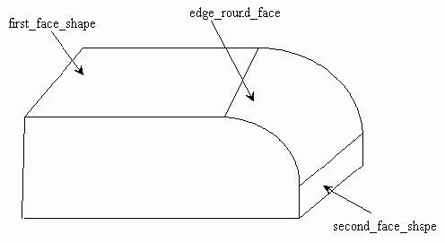
An Edge_round is a type of
Transition_feature
that is a convex circular arc transition between two intersecting surfaces.
The blend surface is tangent to both adjacent surface edges.
An Edge_round may be a
Constant_radius_edge_round.
NOTE
Figure 30
illustrates the Edge_round with an edge_round_face that is not constant radius.
Figure 30 — Edge_round
EXPRESS specification:
            *)

            ENTITY Edge_round

              SUBTYPE OF (Transition_feature);


              edge_round_face : Face_shape_element;


              first_face_shape : Face_shape_element;


              second_face_shape : Face_shape_element;

            END_ENTITY;
(*
Attribute definitions:
edge_round_face:
specifies the circular transition surface between the two edges of two surfaces.
first_face_shape:
specifies one of two surfaces the Edge_round feature will transition between.
second_face_shape:
specifies the other surfaces the Edge_round feature will transition between.
A Face_shape_element is a type of
Shape_element
that is a
Shape_element
definition for a
Face.
EXPRESS specification:
            *)

            ENTITY Face_shape_element

              SUBTYPE OF (Shape_element);
DERIVE

              SELF\Shape_element.product_definitional : BOOLEAN := TRUE;

            END_ENTITY;
(*
Attribute definitions:
product_definitional:
a Face_shape_element shall be definitional.
A Face_shape_element_relationship is a type of
Shape_element_relationship
that is the sequence in which
Face_shape_element
objects are applied.
The Face_shape_element_relationship defines which face is the preceding face and which face is the succeeding face.
EXPRESS specification:
            *)

            ENTITY Face_shape_element_relationship

              SUBTYPE OF (Shape_element_relationship);


              SELF\Shape_element_relationship.relating : Face_shape_element;


              SELF\Shape_element_relationship.related : Face_shape_element;

            END_ENTITY;
(*
Attribute definitions:
relating:
specifies the
Face_shape_element
with the highest precedence.
related:
specifies the
Face_shape_element
with the lesser precedence.
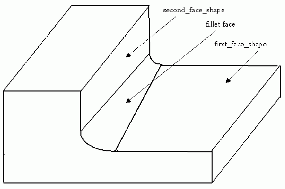
A Fillet is a type of
Transition_feature
that is a concave circular arc transition between two intersecting surfaces.
The blend surface may be tangent adjacent to both surface edges.
A Fillet may be a
Constant_radius_fillet.
NOTE
Figure 31
illustrates a Fillet with a fillet face that is not constant radius.
Figure 31 — Fillet
EXPRESS specification:
            *)

            ENTITY Fillet

              SUBTYPE OF (Transition_feature);


              fillet_face : Face_shape_element;


              first_face_shape : Face_shape_element;


              second_face_shape : Face_shape_element;

            END_ENTITY;
(*
Attribute definitions:
fillet_face:
specifies the circular transition surface between the two edges of two surfaces.
first_face_shape:
specifies one of two surfaces the Fillet feature will transition between.
second_face_shape:
specifies the second of two surfaces the Fillet feature will transition between.
A First_chamfer_offset is an amount of length offset from a face for creating a
Chamfer
feature.
NOTE
Figure 9
illustrates a First_chamfer_offset for a
Chamfer
feature.
EXPRESS specification:
            *)

            ENTITY First_chamfer_offset;


              face_shape : Face_shape_element;


              offset_amount : Numerical_item_with_unit;

            END_ENTITY;
(*
Attribute definitions:
face_shape:
specifies a geometric shape for one of two faces the
Chamfer
feature will transition between.
offset_amount:
specifies a distance from the edge of a face to the start of the
Chamfer.
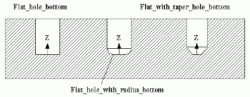
A Flat_hole_bottom is a type of
Blind_bottom_condition
that is the bottom of a
Round_hole
that shall be flat and have no corner radius.
NOTE
Figure 32
illustrates a Flat_hole_bottom for a
Round_hole.
Figure 32 — Flat_hole_bottom
EXPRESS specification:
            *)

            ENTITY Flat_hole_bottom

              SUBTYPE OF (Blind_bottom_condition);

            END_ENTITY;
(*
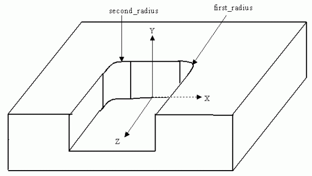
A Flat_slot_end_type is a type of
Slot_end_type
that is an end condition of a slot that shall be a planar shape perpendicular to both adjacent
Slot
wall surfaces.
The intersection of the
Slot
wall surfaces and the end planar shape need not be blended by a radius.
NOTE
Figure 33
illustrates a Flat_slot_end_type for a
Slot.
Figure 33 — Flat_slot_end_type
EXPRESS specification:
            *)

            ENTITY Flat_slot_end_type

              SUBTYPE OF (Slot_end_type);


              first_radius : Numerical_item_with_unit;


              second_radius : Numerical_item_with_unit;

            END_ENTITY;
(*
Attribute definitions:
first_radius:
specifies the circular arc transition between the wall of the
Slot
feature and the planar surface of the Flat_slot_end_type.
The position of the first radius is where the
Slot
wall intersects the Flat_slot_end_type at a positive value along the X-axis.
second_radius:
specifies the circular arc transition between the wall of the
Slot
feature and the planar surface of the Flat_slot_end_type.
The position of the second radius is where the
Slot
wall intersects the Flat_slot_end_type at a negative value along the X-axis.
A Flat_with_radius_hole_bottom is a type of
Blind_bottom_condition
that the bottom of a
Round_hole
is flat and has corner radius that are smaller than the diameter of the
Round_hole.
NOTE
Figure 32
illustrates a Flat_with_radius_hole_bottom for a
Round_hole.
EXPRESS specification:
            *)

            ENTITY Flat_with_radius_hole_bottom

              SUBTYPE OF (Blind_bottom_condition);


              corner_radius : Numerical_item_with_unit;

            END_ENTITY;
(*
Attribute definitions:
corner_radius:
specifies the radius between the side and the floor of a
Round_hole.
A Flat_with_taper_hole_bottom is a type of
Blind_bottom_condition
that the bottom of a
Round_hole
is flat and has a planar taper from the sides of the
Round_hole.
NOTE
Figure 32
illustrates a Flat_with_taper_hole_bottom for a
Round_hole.
EXPRESS specification:
            *)

            ENTITY Flat_with_taper_hole_bottom

              SUBTYPE OF (Blind_bottom_condition);


              taper_diameter : Numerical_item_with_unit;


              final_diameter : Numerical_item_with_unit;

            END_ENTITY;
(*
Attribute definitions:
taper_diameter:
specifies the angle between the side and the floor of a
Round_hole,
measured along the axis inside the
Round_hole.
final_diameter:
specifies the diameter of the
Round_hole
floor which is a diameter smaller than the initial diameter.
A Gear is a type of
Machining_feature
that is a toothed machine part, such as a wheel or cylinder, which meshes with another toothed part to transmit motion
or to change speed or direction.
Each Gear is either a
Catalogue_gear
or a
Defined_gear.
NOTE 1
Vocabulary for gears is defined in ISO 1122-1 [1] and defines the requirements for Gear.
Information used to define the data associated with a gear is defined by ISO 1328-1 [2], ISO 1340 [3], and ISO 2203 [4].
EXPRESS specification:
            *)

            ENTITY Gear

              ABSTRACT SUPERTYPE

            OF (ONEOF (Catalogue_gear,
                                Defined_gear))

              SUBTYPE OF (Machining_feature);


              nominal_tooth_depth : Numerical_item_with_unit;


              reference_pressure_angle : Numerical_item_with_unit;


              profile_shift : Numerical_item_with_unit;


              number_of_teeth : Numerical_item_with_unit;


              face_width : Numerical_item_with_unit;


              tip_diameter : Numerical_item_with_unit;


              normal_attribute : Numerical_item_with_unit;


              applied_shape : Shape_element;


              internal_or_external_gear : BOOLEAN;


              module_or_diametrical_pitch : BOOLEAN;


              root_fillet_radius :
            OPTIONAL
            Numerical_item_with_unit;
WHERE

              WR1: applied_shape.product_definitional = TRUE;

            END_ENTITY;
(*
Attribute definitions:
nominal_tooth_depth:
specifies the radial distance between the tooth tip and root circles.
NOTE 2
Figure 34
illustrates the nominal_tooth_depth for a Gear.
Figure 34 — Gear nominal_tooth_depth
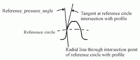
reference_pressure_angle:
specifies the acute angle between a radial line passing through the point of
intersection of the profile with the reference circle and a tangent to the profile at that point.
NOTE 3
Figure 35
illustrates a reference_pressure_angle for a Gear.
Figure 35 — Gear reference_pressure_angle
profile_shift:
specifies the quotient of the rack shift divided by the module.
The rack shift specifies the distance measured along a common normal between the reference cylinder of the gear and
the datum plane of the basic rack when the rack and the gear are superposed so that the flanks of a tooth
of one are tangent to those of the other.
By convention, the profile shift is positive when the datum plane is external to the cylinder and negative when it cuts
it.
This definition is valid for both external and internal gears.
For internal gears, tooth profiles are considered those of the tooth spaces.
NOTE 4
Figure 36
illustrates a profile_shift for a Gear.
Figure 36 — Gear profile_shift
number_of_teeth:
specifies the number of teeth in the circumference produced on the part surface.
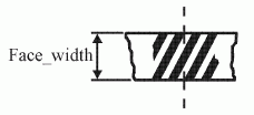
face_width:
specifies a width over the toothed part of a gear measured along a generator of the reference cylinder.
NOTE 5
Figure 37
illustrates a face_width for a Gear.
Figure 37 — Gear face_width
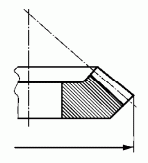
tip_diameter:
specifies the diameter of the tip circle.
NOTE 6
Figure 38
illustrates a tip_diameter for a Gear.
Figure 38 — Gear tip_diameter
normal_attribute:
specifies the module when the value of module_or_diametrical_pitch is 'module' or
the diametral pitch when the value of module_or_diametrical_pitch is 'diameter pitch'.
For a spur gear, the normal_attribute is the module or diametral pitch, requiring no qualification;
for a helical gear, the normal_attribute specifies the normal module or the normal diametral pitch.
applied_shape:
specifies a base shape for applying the Gear feature.
internal_or_external_gear:
specifies whether the gear teeth are applied to an internal surface or an external surface.
module_or_diametrical_pitch:
specifies which of either the module or diametral pitch of a gear is specified by the normal_attribute.
The module of a spur gear is the quotient of the pitch at the reference surface divided by π.
The normal module of a helical gear is the quotient of the normal pitch divided by π.
The normal pitch is the pitch at the reference surface measured along the arc of a co-cylindrical normal helix,
lying between the tooth traces of consecutive corresponding flanks.
The diametral pitch is the quotient of the number π divided by the pitch, or the quotient of the number of
teeth divided by the reference diameter.
The normal diametral pitch of a helical gear is the quotient of the number π divided by the normal pitch,
or the quotient of the number of teeth divided by the product of the reference diameter and the cosine of the helix angle.
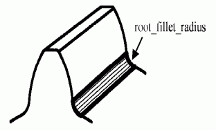
root_fillet_radius:
specifies the acceptable radius of the surface between the usable flank and the root surface. The value of this attribute
need not be specified.
NOTE 7
Figure 39
illustrates a root_fillet_radius for a Gear.
Figure 39 — Gear root_fillet_radius
Formal propositions:
WR1:
a Gear shall be definitional.
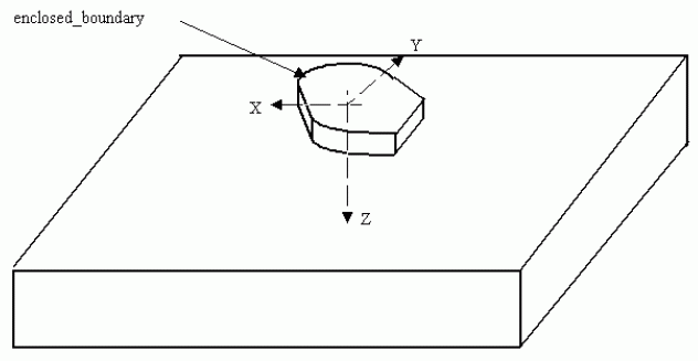
A General_boss is a type of
Boss
that is an enclosed volume bounded by an arbitrary shape.
NOTE
Figure 40
illustrates the General_boss.
Figure 40 — General_boss
EXPRESS specification:
            *)

            ENTITY General_boss

              SUBTYPE OF (Boss);


              enclosed_boundary : Closed_profile;


              change_in_boundary :
            OPTIONAL
            angle_or_directed_taper;

            END_ENTITY;
(*
Attribute definitions:
enclosed_boundary:
specifies an outline or shape that bounds an enclosed area with no opening for a General_boss.
The
Closed_profile
specifies the area required by a General_boss.
The placement of the enclosed_boundary shall be with the origin of the
Closed_profile
at the origin of the General_boss.
The X-axis and Y-axis of the profile shall be the same as the X-axis and Y-axis of the General_boss.
change_in_boundary:
specifies a taper that defines the change in shape of the General_boss.
The value of this attribute need not be specified.
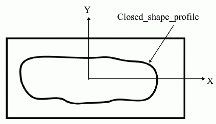
A General_closed_profile is a type of
Closed_profile
that is an enclosed area bounded by an arbitrary shape.
The orientation is defined by the explicit geometry of the shape.
NOTE
Figure 41
illustrates a General_closed_profile.
Figure 41 — General_closed_profile
EXPRESS specification:
            *)

            ENTITY General_closed_profile

              SUBTYPE OF (Closed_profile);


              closed_profile_shape : Path_element;

            END_ENTITY;
(*
Attribute definitions:
closed_profile_shape:
specifies a closed curve that defines the arbitrary shape of the profile.
A General_cutout is a type of
Cutout_feature
that is a volume of arbitrary shape removed from the part and shall pass through two faces of the part.
A General_cutout is similar in definition to a
General_pocket,
but differ in the type of process required to manufacture.
EXPRESS specification:
            *)

            ENTITY General_cutout

              SUBTYPE OF (Cutout_feature);


              boundary : Profile;

            END_ENTITY;
(*
Attribute definitions:
boundary:
specifies an outline or shape that is an area that may be closed or partially open.
The profile specifies the area required by a General_cutout.
The placement of the boundary shall be with the origin of the
Profile
at the origin of the General_cutout.
The X-axis and Y-axis of the profile shall be the same as the X-axis and Y-axis of the General_cutout.
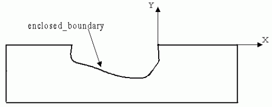
A General_open_profile is a type of
Open_profile
that is specified by a shape bounded by an arbitrary planar shape.
The orientation is defined by the explicit geometry of the shape.
NOTE
Figure 42
illustrates a General_open_profile.
Figure 42 — General_open_profile
EXPRESS specification:
            *)

            ENTITY General_open_profile

              SUBTYPE OF (Open_profile);


              enclosed_boundary : Path_element;

            END_ENTITY;
(*
Attribute definitions:
enclosed_boundary:
specifies a curve with no enclosing bounds that defines the arbitrary planar shape of the profile.
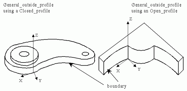
A General_outside_profile is a type of
Profile_feature
that is specified the removal volume of raw stock or other excess material of arbitrary shape from the outside shape of the
part.
The General_outside_profile feature may remove material from the entire outside shape or some portion of the shape.
A single part may have several General_outside_profile objects, with the Z-axes of the coordinate
systems of the General_outside_profile objects pointing in any direction.
NOTE
Figure 43
illustrates a General_outside_profile.
Figure 43 — General_outside_profile
EXPRESS specification:
            *)

            ENTITY General_outside_profile

              SUBTYPE OF (Profile_feature);


              boundary : Profile;

            END_ENTITY;
(*
Attribute definitions:
boundary:
specifies a profile that identifies the outside shape of the part.
The placement of the boundary shall be with the origin of the profile at the origin of the General_outside_profile feature.
The X-axis and Y-axis of the profile shall be the same as the X-axis and Y-axis of the feature.
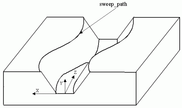
A General_path_feature_component is a type of
Path_feature_component
that is a direction of travel along an arbitrary curve.
NOTE
Figure 44
illustrates a
Slot
feature with a
Square_u_profile
and a General_path_feature_component.
The path has the same orientation as the
Slot
feature.
The orientation of the profile positions it to the orientation of the
Slot
feature. The
Square_u_profile
has orientation to position it at the same position as the
Slot
feature.
Figure 44 — General_path_feature_component
EXPRESS specification:
            *)

            ENTITY General_path_feature_component

              SUBTYPE OF (Path_feature_component);


              sweep_path : Path_element;

            END_ENTITY;
(*
Attribute definitions:
sweep_path:
specifies a continues set of curves that define an arbitrary direction of travel.
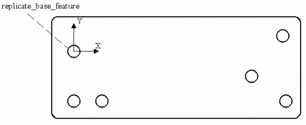
A General_pattern is a type of
Replicate_feature
that is a base shape component and a list of arbitrary placements to arrange identical copies of the base feature.
The placement of all instances of the base feature are relative to the
Replicate_feature
coordinate system.
NOTE
Figure 45
illustrates a General_pattern of
Round_hole
features.
Figure 45 — General_pattern
EXPRESS specification:
            *)

            ENTITY General_pattern

              SUBTYPE OF (Replicate_feature);


              feature_placement : SET[1:?] OF Axis_placement;

            END_ENTITY;
(*
Attribute definitions:
feature_placement:
specifies a set of axis and positions to place a base feature in the General_pattern.
A General_pattern is defined as one base feature and many placements allowing the base feature to be
placed several times in a random pattern.
There may be more than one feature_placement for a General_pattern.
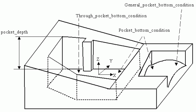
A General_pocket is a type of
Pocket
that is a volume of arbitrary shape removed from the part.
NOTE
Figure 46
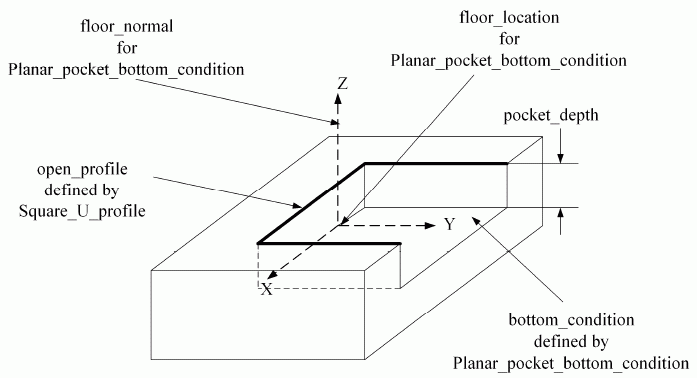
illustrates a General_pocket with a
Through_pocket_bottom_condition
and a pocket depth that defines the highest point of the pocket.
Figure 46 — General_pocket
EXPRESS specification:
            *)

            ENTITY General_pocket

              SUBTYPE OF (Pocket);


              volume_not_removed : SET[0:?] OF volume_select;


              boundary : Profile;

            END_ENTITY;
(*
Attribute definitions:
volume_not_removed:
specifies an amount of material that is not to be removed from the pocket.
The
Boss
feature defines the shape of the material that is to remain in the pocket.
boundary:
specifies an outline or shape that is an area that may be closed or partially open.
The profile specifies the area required by a General_pocket.
The placement of the boundary shall be with the origin of the
Profile
at the origin of the General_pocket.
The X-axis and Y-axis of the profile shall be the same as the X-axis and Y-axis of the General_pocket.
A General_pocket_bottom_condition is a type of
Pocket_bottom_condition
that specifies an enclosed area bounded by an arbitrary shape.
NOTE
Figure 46
illustrates the General_pocket_bottom_condition applied to a
General_pocket
with an
Open_profile.
EXPRESS specification:
            *)

            ENTITY General_pocket_bottom_condition

              SUBTYPE OF (Pocket_bottom_condition);


              floor : Face_shape_element;


              floor_radius :
            OPTIONAL
            Numerical_item_with_unit;

            END_ENTITY;
(*
Attribute definitions:
floor:
specifies the face at the bottom of a
Pocket
feature, adjacent to all the pocket walls.
floor_radius:
specifies the amount of curvature for an arc between the bottom and the sides of a pocket feature.
The value of this attribute need not be specified.
A General_profile_floor is a type of
Profile_floor
that specifies an enclosed area bounded by an arbitrary shape.
NOTE
Figure 81
illustrates a
Shape_profile
with a General_profile_floor.
EXPRESS specification:
            *)

            ENTITY General_profile_floor

              SUBTYPE OF (Profile_floor);


              floor : Face_shape_element;

            END_ENTITY;
(*
Attribute definitions:
floor:
specifies the face at the bottom of a General_profile_floor feature, adjacent to all the
Shape_profile
walls.
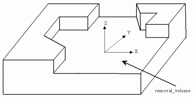
A General_removal_volume is a type of
Multi_axis_feature
that is an enclosed volume of arbitrary shape that shall be removed from the part.
The position and orientation shall be determined from the shape defining geometry.
NOTE
Figure 47
illustrates a General_removal_volume.
Figure 47 — General_removal_volume
EXPRESS specification:
            *)

            ENTITY General_removal_volume

              SUBTYPE OF (Multi_axis_feature);


              removal_volume : SET[1:?] OF Shape_element;

            END_ENTITY;
(*
Attribute definitions:
removal_volume:
specifies the arbitrary shape to be removed.
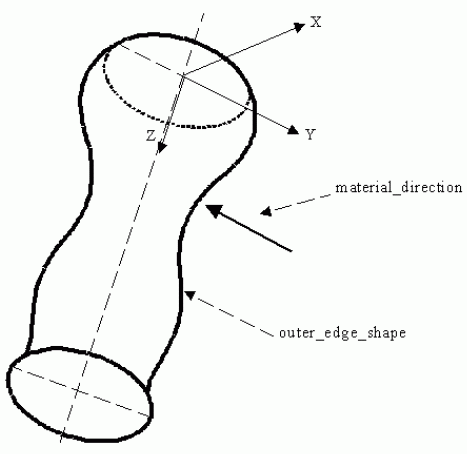
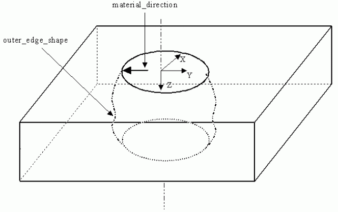
A General_revolution is a type of
Revolved_feature
that is an arbitrary planar shape swept one complete revolution about an axis.
The arbitrary planar shape shall be finite in length, coplanar with the axis of revolution, and shall not intersect the axis
of revolution.
The General_revolution may be either an outer shape of a part or a volume removal, depending on the material direction.
NOTE
Figure 48
illustrates a General_revolution for an outer shape, the material direction points to the material side.
Figure 49
illustrates a General_revolution for a volume removal.
Figure 48 — General_revolution for an outer shape
Figure 49 — General_revolution for a volume removal
EXPRESS specification:
            *)

            ENTITY General_revolution

              SUBTYPE OF (Revolved_feature);


              outer_edge_shape : General_open_profile;

            END_ENTITY;
(*
Attribute definitions:
outer_edge_shape:
specifies an outline or shape that shall be revolved about an axis.
The
General_open_profile
specifies the outer edge shape required by a General_revolution.
The placement of the outer_edge_shape shall be on the Y-axis of the General_revolution at a specified distance away from
the origin of the General_revolution.
The X-axis and Y-axis of the profile shall be the same as the Y-axis and Z-axis of the General_revolution.
A General_rib_top_floor is a type of
Rib_top_floor
that specifies an enclosed area bounded by an arbitrary shape.
The floor defining shapes may be defined in a sequence.
EXPRESS specification:
            *)

            ENTITY General_rib_top_floor

              SUBTYPE OF (Rib_top_floor);


              rib_top_face : SET[1:?] OF Face_shape_element;

            END_ENTITY;
(*
Attribute definitions:
rib_top_face:
specifies a set of faces at the bottom of a
Rib_top.
The order of the faces is achieved using a
Face_shape_element_relationship.
A General_shape_profile is a type of
Shape_profile
that is a volume of arbitrary shape which defines a portion of the part.
EXPRESS specification:
            *)

            ENTITY General_shape_profile

              SUBTYPE OF (Shape_profile);


              profile_boundary : Profile;

            END_ENTITY;
(*
Attribute definitions:
profile_boundary:
specifies the outline of the
Shape_profile
feature.
The outline defines an area that may or may not be entirely enclosed.
The placement of the profile_boundary shall be with the origin of the
Path_feature_component,
that which defines the profile, at the origin of the General_shape_profile.
The X-axis and Y-axis of the profile shall be the same as the X-axis and Y-axis of the General_shape_profile.
A General_top_condition is a type of
Boss_top_condition
that specifies an enclosed area bounded by an arbitrary shape that defines the top of a
Boss
feature.
EXPRESS specification:
            *)

            ENTITY General_top_condition

              SUBTYPE OF (Boss_top_condition);


              top_face : Face_shape_element;

            END_ENTITY;
(*
Attribute definitions:
top_face:
specifies a face at the top of a
Boss
feature, adjacent to the
Boss
sides.
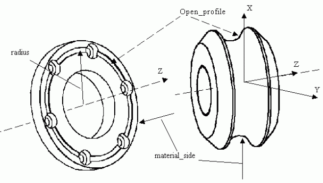
A Groove is a type of
Revolved_feature
that is a narrow channel or depression that is swept through one complete revolution about an axis.
NOTE
Figure 50
illustrates two Groove features.
The face shape that has the Groove applied to it is determined by the profile orientation.
Figure 50 — Groove
EXPRESS specification:
            *)

            ENTITY Groove

              SUBTYPE OF (Revolved_feature);


              sweep : Open_profile;

            END_ENTITY;
(*
Attribute definitions:
sweep:
specifies an outline or shape that shall be revolved about an axis.
The
Open_profile
specifies the sweep shape required by a Groove.
The placement of the profile shall be along the X-axis of the Groove at a specified distance away from the origin.
The orientation of the
Open_profile
is independent of the orientation of the Groove feature.
The Groove feature may be defined on different faces of a part depending on the orientation of the profile.
A Helical_bevel_gear is a type of
Bevel_gear
where the tooth traces are non-cylindrical helices, joining the definitions of as of a
Bevel_gear
and a
Helical_gear.
EXPRESS specification:
            *)

            ENTITY Helical_bevel_gear

              SUBTYPE OF (Bevel_gear);


              reference_helix_agle : Numerical_item_with_unit;


              left_or_right_hand_tooth : BOOLEAN;

            END_ENTITY;
(*
Attribute definitions:
reference_helix_agle:
specifies the acute angle between the tangent to the tooth trace of a straight helical
gear and the straight generator of the reference cylinder on which it lies.
left_or_right_hand_tooth:
specifies a description of whether the gear teeth are right or left handed.
Right-hand teeth are teeth whose successive transverse profiles show clockwise displacement with
increasing distance from an observer looking along the straight-line generators of the reference surface
Left-hand teeth are teeth whose successive transverse profiles show anti-clockwise displacement with
increasing distance from an observer looking along the straight-line generators of the reference surface.
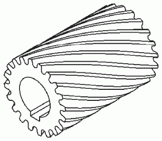
A Helical_gear is a type of
Defined_gear
that is a cylindrical gear whose tooth traces are helices.
NOTE 1
Figure 51
illustrates the Helical_gear.
Figure 51 — Helical_gear
EXPRESS specification:
            *)

            ENTITY Helical_gear

              SUBTYPE OF (Defined_gear);


              left_or_right_hand_tooth : BOOLEAN;


              reference_helix_angle : Numerical_item_with_unit;

            END_ENTITY;
(*
Attribute definitions:
left_or_right_hand_tooth:
specifies a description of whether the gear teeth are right or left handed.
Right-hand teeth are teeth whose successive transverse profiles show clockwise displacement with
increasing distance from an observer looking along the straight-line generators of the reference surface.
Left-hand teeth are teeth whose successive transverse profiles show anti-clockwise displacement with
increasing distance from an observer looking along the straight-line generators of the reference surface.
NOTE 2
Figure 52
illustrates left or right-hand teeth for a Helical_gear.
Figure 52 — Helical_gear left_or_right_hand_tooth
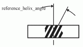
reference_helix_angle:
the acute angle between the tangent to the tooth trace of a straight helical
gear and the straight generator of the reference cylinder on which it lies.
NOTE 3
Figure 53
illustrates a reference_helix_angle for a Helical_gear.
Figure 53 — Helical_gear reference_helix_angle
A Hole is a type of
Multi_axis_feature
that is the removal of a cylindrical volume from a part.
The Hole may be positioned at its bottom with the Z-axis in the direction out of the
Hole or at a position at the top of the hole with the Z-axis in the direction into the part.
EXPRESS specification:
            *)

            ENTITY Hole
            ABSTRACT

              SUBTYPE OF (Multi_axis_feature);

            END_ENTITY;
(*
An Instanced_manufacturing_feature is a type of
Instanced_feature.
EXPRESS specification:
            *)

            ENTITY Instanced_manufacturing_feature

              SUBTYPE OF (Instanced_feature);


              definition : Manufacturing_feature;

            END_ENTITY;
(*
Attribute definitions:
definition:
specifies the role of the
Manufacturing_feature
for the Instanced_manufacturing_feature.
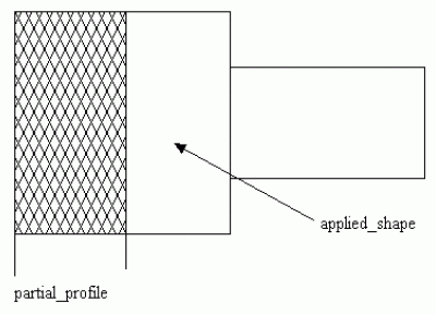
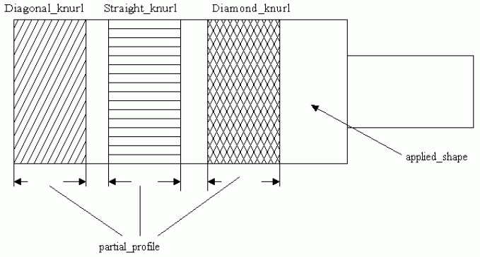
A Knurl is a type of
Machining_feature
that is a scoring pattern made by a series of small ridges or beads on a metal surface.
Each Knurl is either a
Catalogue_knurl
or a
Turned_knurl.
NOTE
Figure 54
illustrates a Knurl types.
Figure 54 — Knurl
EXPRESS specification:
            *)

            ENTITY Knurl

              ABSTRACT SUPERTYPE

            OF (ONEOF (Catalogue_knurl,
                                Turned_knurl))

              SUBTYPE OF (Machining_feature);


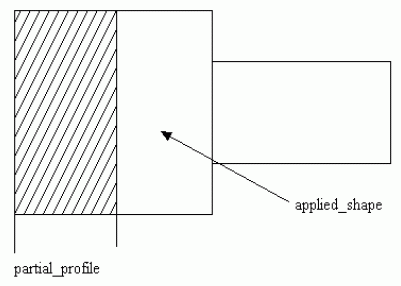
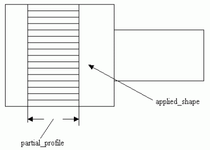
              partial_profile :
            OPTIONAL
            Partial_area_definition;


              applied_shape : Shape_element;
WHERE

              WR1: applied_shape.product_definitional = TRUE;

            END_ENTITY;
(*
Attribute definitions:
partial_profile:
specifies the placement and length of a surface to apply a Knurl feature.
The value of this attribute need not be specified.
applied_shape:
specifies a base shape for applying the Knurl feature.
Formal propositions:
WR1:
a Knurl shall be definitional.
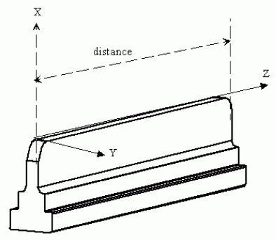
A Linear_path_feature_component is a type of
Path_feature_component
that is a direction of travel along a line.
NOTE
Figure 55
illustrates a
Machining_feature
with a Linear_path_feature_component. This path has the same orientation as the feature.
Figure 55 — Linear_path_feature_component
EXPRESS specification:
            *)

            ENTITY Linear_path_feature_component

              SUBTYPE OF (Path_feature_component);


              distance : length_measure;


              direction : Direction_element;

            END_ENTITY;
(*
Attribute definitions:
distance:
specifies the length of the path.
direction:
specifies a vector which indicates the direction of the path starting from the path placement.
A Linear_profile is a type of
Open_profile
that is a straight-line of a specified length.
The Linear_profile shall have orientation parallel to the X-axis.
NOTE
Figure 56
illustrates a Linear_profile that is being applied to the
Planar_face
feature.
Figure 56 — Linear_profile
EXPRESS specification:
            *)

            ENTITY Linear_profile

              SUBTYPE OF (Open_profile);


              profile_length : Numerical_item_with_unit;

            END_ENTITY;
(*
Attribute definitions:
profile_length:
specifies the length of the profile.
A Location_element is a type of
Shape_element
that is a
Shape_element
representation for a reference point.
EXPRESS specification:
            *)

            ENTITY Location_element

              SUBTYPE OF (Shape_element);

            END_ENTITY;
(*
A Loop_slot_end_type is an end conditions of a slot that is a closed loop.
The start point and end point of the
Slot
are the same point, the
Slot
has no end openings.
EXPRESS specification:
            *)

            ENTITY Loop_slot_end_type;

            END_ENTITY;
(*
A Machining_feature is a type of
Manufacturing_feature
that identifies a volume of material that shall be removed to obtain the final part geometry from the initial stock.
Machining_feature requires both direction and location in placing them on a part.
Each Machining_feature is either a
Compound_feature,
a
Gear,
a
Knurl,
a
Marking_feature,
a
Multi_axis_feature,
an
Outer_round,
a
Revolved_feature,
a
Spherical_cap,
or a
Thread.
EXPRESS specification:
            *)

            ENTITY Machining_feature

              ABSTRACT SUPERTYPE

            OF (ONEOF (Compound_feature,
                                Gear,
                                Knurl,
                                Marking_feature,
                                Multi_axis_feature,
                                Outer_round,
                                Revolved_feature,
                                Spherical_cap,
                                Thread))

              SUBTYPE OF (Manufacturing_feature);


              placement : Axis_placement_3d;

            END_ENTITY;
(*
Attribute definitions:
placement:
specifies the position and orientation of a Machining_feature relative to the base shape for a part.
A Manufacturing_feature is a type of
Shape_feature_definition
that identifies the types of features necessary to manufacture a machined part.
Each Manufacturing_feature is either a
Machining_feature,
a
Replicate_feature,
or a
Transition_feature.
EXPRESS specification:
            *)

            ENTITY Manufacturing_feature

              ABSTRACT SUPERTYPE

            OF (ONEOF (Machining_feature,
                                Replicate_feature,
                                Transition_feature))

              SUBTYPE OF (Shape_feature_definition);

            END_ENTITY;
(*
A Manufacturing_feature_group is a type of
Group
that is a collection of manufacturing features with a usage identification.
A Manufacturing_feature_group shall allow for the collection of collections.
EXAMPLE
A Manufacturing_feature_group may be used to group together all the hold down holes for a part.
EXPRESS specification:
            *)

            ENTITY Manufacturing_feature_group

              SUBTYPE OF (Group);


              SELF\Group.elements : SET[1:?] OF manufacturing_group_select;

            END_ENTITY;
(*
Attribute definitions:
elements:
specifies the set of
Manufacturing_feature
or other Manufacturing_feature_groups to be grouped.
A Marking_feature is a type of
Machining_feature
that is one or more text characters on a surface of a part.
Each Marking_feature is either a
Catalogue_marking
or a
Defined_marking.
EXPRESS specification:
            *)

            ENTITY Marking_feature

              ABSTRACT SUPERTYPE

            OF (ONEOF (Catalogue_marking,
                                Defined_marking))

              SUBTYPE OF (Machining_feature);


              text : text;


              applied_to_shape : Shape_element;

            END_ENTITY;
(*
Attribute definitions:
text:
specifies the characters that will be applied to the part.
applied_to_shape:
specifies a base shape for applying the Marking_feature feature.
A Multi_axis_feature is a type of
Machining_feature
that identifies milling features for a part, and not turned features.
Each Multi_axis_feature may be one of the following: a
Boss,
a
General_removal_volume,
a
Hole,
a
Planar_face,
a
Pocket,
a
Profile_feature,
a
Protrusion,
a
Rib_top,
a
Rounded_end,
a
Slot,
or a
Step.
EXPRESS specification:
            *)

            ENTITY Multi_axis_feature

              SUPERTYPE OF (ONEOF (Boss,
                       General_removal_volume,
                       Hole,
                       Planar_face,
                       Pocket,
                       Profile_feature,
                       Protrusion,
                       Rib_top,
                       Rounded_end,
                       Slot,
                       Step))

              SUBTYPE OF (Machining_feature);


              maximum_feature_limit :
            OPTIONAL
            Planar_element;

            END_ENTITY;
(*
Attribute definitions:
maximum_feature_limit:
specifies a planar limitation for a feature.
No portion of the feature shall exist beyond this planar definition.
The normal to the plane shall be in the direction away from the
Machining_feature.
The value of this attribute need not be specified.
An Ngon_profile is a type of
Closed_profile
that is an enclosed area bounded by three or more connected straight-line sides.
The orientation is at the centre of the profile with one side of the ngon parallel to the X-axis crossing the Y-axis at a
negative value.
NOTE
Figure 57
illustrates the Ngon_profile.
Figure 57 — Ngon_profile
EXPRESS specification:
            *)

            ENTITY Ngon_profile

              SUBTYPE OF (Closed_profile);


              diameter : Numerical_item_with_unit;


              number_of_sides : Numerical_item_with_unit;


              corner_radius :
            OPTIONAL
            Numerical_item_with_unit;


              circumscribed_or_across_flat : BOOLEAN;

            END_ENTITY;
(*
Attribute definitions:
diameter:
specifies the size of either the circumscribed diameter, or the diameter across the flats.
number_of_sides:
specifies how many sides are needed for the Ngon.
corner_radius:
specifies the size of an arc blend between two sides of the ngon.
The value of this attribute need not be specified.
circumscribed_or_across_flat:
specifies the type of diameter being used to define the Ngon_profile.
Circumscribed is the diameter that the polygon with any number of sides fits inside of, with the corners on the circle that
defines the diameter.
Across flats, is the diameter that fits inside of the Ngon_profile with the sides of the shape being tangent to the circle
that defines the diameter.
An Open_profile is a type of
Profile
that is an outline or shape with no enclosing or confining bounds.
The open ends of the profile may extend infinitely.
Each Open_profile is either a
General_open_profile,
a
Linear_profile,
a
Partial_circular_profile,
a
Rounded_u_profile,
a
Square_u_profile,
a
Tee_profile,
or a
Vee_profile.
EXPRESS specification:
            *)

            ENTITY Open_profile

              ABSTRACT SUPERTYPE

            OF (ONEOF (General_open_profile,
                                Linear_profile,
                                Partial_circular_profile,
                                Rounded_u_profile,
                                Square_u_profile,
                                Tee_profile,
                                Vee_profile))

              SUBTYPE OF (Profile);


              profile_limit :
            OPTIONAL
            Planar_element;

            END_ENTITY;
(*
Attribute definitions:
profile_limit:
specifies a planar limitation for a feature.
No portion of the profile shall exist beyond this planar definition.
The normal to the plane shall be in the direction away from the
Open_profile.
The value of this attribute need not be specified.
An Open_slot is a type of
Slot
that has a course of travel defined by a
Path_feature_component
that is open and has openings.
EXPRESS specification:
            *)

            ENTITY Open_slot

              SUBTYPE OF (Slot);


              course_of_travel : Path_feature_component;


              end_conditions : SET[2:2] OF Slot_end_type;

            END_ENTITY;
(*
Attribute definitions:
course_of_travel:
specifies a 3D space curve, that when combine with a
Profile,
creates the shape of the
Slot.
end_conditions:
specifies the type of implicit shape at the ends of the
Slot.
An Open_slot_end_type is a type of
Slot_end_type
that is an end condition of a slot that shall pass through the end of the part.
NOTE
Figure 58
illustrates a slot with two Open_slot_end_type objects.
Figure 58 — Open_slot_end_type
EXPRESS specification:
            *)

            ENTITY Open_slot_end_type

              SUBTYPE OF (Slot_end_type);

            END_ENTITY;
(*
An Outer_diameter is a type of
Outer_round
that is a sweeping of an outline specified by a line segment one complete revolution about an axis.
The line is finite in length, coplanar with the axis.
An Outer_diameter may have a constant diameter around the axis of rotation, or it may be tapered.
NOTE
Figure 59
illustrates the Outer_diameter with and without a taper.
Figure 59 — Outer_diameter
EXPRESS specification:
            *)

            ENTITY Outer_diameter

              SUBTYPE OF (Outer_round);


              feature_length : Numerical_item_with_unit;


              diameter : Numerical_item_with_unit;


              reduced_size : taper_select;

            END_ENTITY;
(*
Attribute definitions:
feature_length:
specifies the size of an Outer_diameter feature, measured along the feature's axis.
diameter:
specifies the maximum diametric size of an Outer_diameter feature.
reduced_size:
specifies the constant change in the Outer_diameter along the feature length.
An Outer_diameter_to_shoulder is a type of
Outer_round
that is a sweeping of a shape one complete revolution about an axis.
The shape shall be specified by two lines that connect at a point and extend infinitely.
The enclosed angle shall be smaller than a straight angle.
The intersection of the two lines need not be blended with a radius.
NOTE
Figure 60
illustrates the Outer_diameter_to_shoulder.
Figure 60 — Outer_diameter_to_shoulder
EXPRESS specification:
            *)

            ENTITY Outer_diameter_to_shoulder

              SUBTYPE OF (Outer_round);


              feature_length : Numerical_item_with_unit;


              diameter : Numerical_item_with_unit;


              v_shape_boundary : Vee_profile;

            END_ENTITY;
(*
Attribute definitions:
feature_length:
specifies the size of an Outer_diameter_to_shoulder, measured along the feature's axis.
diameter:
specifies the size of the part at the point of the Vee,
or where the two sides come together, swept about an axis of rotation.
v_shape_boundary:
specifies an outline or shape that shall be revolved about an axis.
The
Vee_profile
specifies the revolved shape required by an Outer_diameter_to_shoulder.
The placement of the profile shall be along the X-axis of the Outer_diameter_to_shoulder at a specified distance away from the origin.
The orientation of the Y-axis of the
Vee_profile
shall be the same as the Y-axis of the Outer_diameter_to_shoulder and the X-axis of the
Vee_profile
shall be the same as the Z-axis of the Outer_diameter_to_shoulder.
An Outer_round is a type of
Machining_feature
that is an outline or significant shape that is swept through a complete revolution about an axis.
Each Outer_round is either an
Outer_diameter
or an
Outer_diameter_to_shoulder.
The axis of revolution shall be the same as the Z-axis of the feature.
EXPRESS specification:
            *)

            ENTITY Outer_round

              ABSTRACT SUPERTYPE

            OF (ONEOF (Outer_diameter,
                                Outer_diameter_to_shoulder))

              SUBTYPE OF (Machining_feature);

            END_ENTITY;
(*
A Partial_area_definition is a limitations of a surface for applying a
Machining_feature.
Thread
and
Knurl
features are applied to cylindrical shapes.
Partial_area_definition places a limitation on how much and where to apply the feature on the cylindrical shape.
NOTE
Figure 8
and
Figure 26
illustrates a
Defined_thread
with a Partial_area_definition.
The drawing call out '5.12 MIN.THREAD' defines the amount of cylindrical shape that has the thread applied.
EXPRESS specification:
            *)

            ENTITY Partial_area_definition;


              maximum_length :
            OPTIONAL
            Numerical_item_with_unit;


              effective_length : Numerical_item_with_unit;


              placement : Axis_placement;

            END_ENTITY;
(*
Attribute definitions:
maximum_length:
specifies the dimension along a surface to apply a feature.
A
Thread
is a type of
Machining_feature
that is applied to a surface.
The dimensional distance limits the length along the surface axis for defining these feature objects.
The value of this attribute need not be specified.
effective_length:
specifies the length of the thread which is usable by the feature.
When applied to a knurl the effective_length defines the overall length of the knurl.
placement:
specifies where to locate the Partial_area_definition.
A Partial_circular_path_feature_component is a type of
Circular_path_feature_component
that is a direction of travel along an arc of constant radius around an axis.
The path shall begin and end at different points on the arc.
NOTE
Figure 61
illustrates two
Slot
feature with a
Square_u_profile
and a Partial_circular_path_feature_component.
Figure 61 — Partial_circular_path_feature_component
EXPRESS specification:
            *)

            ENTITY Partial_circular_path_feature_component

              SUBTYPE OF (Circular_path_feature_component);


              sweep_angle : length_measure;

            END_ENTITY;
(*
Attribute definitions:
sweep_angle:
specifies the size of the angle to define an arc shaped path.
A Partial_circular_profile is a type of
Open_profile
that is specified by an arc.
The arc shall be a constant radius swept about a point.
The orientation of the profile shall be positioned at the origin of the arc, with one end point of the arc on the X-axis.
NOTE
Figure 62
illustrates a Partial_circular_profile.
Figure 62 — Partial_circular_profile
EXPRESS specification:
            *)

            ENTITY Partial_circular_profile

              SUBTYPE OF (Open_profile);


              sweep_angle : Numerical_item_with_unit;


              radius : Numerical_item_with_unit;

            END_ENTITY;
(*
Attribute definitions:
sweep_angle:
specifies the size of the angle to define a circular shaped profile.
radius:
specifies the size of the arc to define a Partial_circular_profile.
A Partial_circular_shape_profile is a type of
Shape_profile
which defines a volume that is not enclosed on all sides.
EXPRESS specification:
            *)

            ENTITY Partial_circular_shape_profile

              SUBTYPE OF (Shape_profile);


              open_boundary : Partial_circular_profile;

            END_ENTITY;
(*
Attribute definitions:
open_boundary:
specifies the outline of the
Shape_profile
feature.
The outline defines an area that shall be circular and shall not be enclosed.
The placement of the open_boundary shall be with the origin of the
Path_feature_component,
that defines the profile, at the origin of the Partial_circular_shape_profile.
The X-axis and Y-axis of the profile shall be the same as the X-axis and Y-axis of the Partial_circular_shape_profile.
A Path_element is a type of
Shape_element
that is a continuous set of geometric curve that represent the path for a
Machining_feature.
EXPRESS specification:
            *)

            ENTITY Path_element

              SUBTYPE OF (Shape_element);

            END_ENTITY;
(*
A Path_feature_component is a type of
Shape_element.
A Path_feature_component is a continuous set of curves that define a direction of travel.
These curves do not intersect or duplicate themselves.
A Path_feature_component shall have its own orientation which may be the same orientation as the
Machining_feature
which requires it as a part of a feature definition.
The orientation of a Path_feature_component may be the same orientation as the
Machining_feature.
Each Path_feature_component is either a
Circular_path_feature_component,
a
General_path_feature_component,
or a
Linear_path_feature_component.
EXPRESS specification:
            *)

            ENTITY Path_feature_component

              ABSTRACT SUPERTYPE

            OF (ONEOF (Circular_path_feature_component,
                                General_path_feature_component,
                                Linear_path_feature_component))

              SUBTYPE OF (Shape_element);


              placement : Axis_placement;

            END_ENTITY;
(*
Attribute definitions:
placement:
specifies where to locate the Path_feature_component.
A Planar_element is a type of
Shape_element
that is a flat surface.
EXPRESS specification:
            *)

            ENTITY Planar_element

              SUBTYPE OF (Shape_element);


              normal : Direction_element;


              location : Location_element;

            END_ENTITY;
(*
Attribute definitions:
normal:
specifies the vector which indicates the normal of a plane being defined for the planar surface.
location:
specifies the position of the planar surface.
A Planar_face is a type of
Multi_axis_feature
that is an unbounded planar cut of a part.
The Planar_face shall have an orientation such that the Z-axis is the direction away from the part.
NOTE
Figure 63
illustrates the Planar_face.
Figure 63 — Planar_face
EXPRESS specification:
            *)

            ENTITY Planar_face

              SUBTYPE OF (Multi_axis_feature);


              removal_boundary : Linear_profile;


              course_of_travel : Linear_path_feature_component;


              face_boundary :
            OPTIONAL
            Closed_profile;


              removal_direction : Direction_element;


              volume_not_removed : SET[0:?] OF volume_select;


              removal_depth :
            OPTIONAL
            Numerical_item_with_unit;

            END_ENTITY;
(*
Attribute definitions:
removal_boundary:
specifies a line with direction and magnitude that when swept along a path defines the area on a part for volume removal.
The orientation and placement of the
Linear_profile
shall be the same as the Planar_face.
course_of_travel:
specifies a straight-line with magnitude and direction.
The placement and orientation of the
Linear_path_feature_component
shall be the same as the Planar_face feature.
face_boundary:
specifies the complete or partial outside final shape of the part after the planar cut has been applied.
The value of this attribute need not be specified.
removal_direction:
specifies the direction of material removal from the Planar_face feature.
volume_not_removed:
specifies an amount of material that is not to be removed from the Planar_face.
The
Boss
or
Protrusion
feature define the shape of the material that is to remain in the Planar_face.
removal_depth:
specifies a measured distance from the bottom of a point that is outside of the Planar_face.
The removal_depth places a limitation on the Planar_face definition so not to interfere with other features that might be nearby.
The placement and orientation of the
Linear_path_feature_component
that defines removal_depth shall be the same as the Planar_face.
The value of this attribute need not be specified.
EXAMPLE
If a portion of the part should extend over the top of the Planar_face, the depth value would not interfere with it.
A Planar_pocket_bottom_condition is a type of
Pocket_bottom_condition
that characterizes the bottom of a pocket which is flat.
NOTE 1
Figure 73
illustrates the
Rectangular_open_pocket
with a Planar_pocket_bottom_condition.
Figure 69
illustrates a
Rectangular_closed_pocket
with a Planar_pocket_bottom_condition.
EXPRESS specification:
            *)

            ENTITY Planar_pocket_bottom_condition

              SUBTYPE OF (Pocket_bottom_condition);


              floor_normal : Direction_element;


              floor_location : Location_element;


              floor_radius :
            OPTIONAL
            Numerical_item_with_unit;

            END_ENTITY;
(*
Attribute definitions:
floor_normal:
specifies the vector which indicates the normal of a plane being defined for the bottom of a pocket.
NOTE 2
Figure 73
illustrates the
Rectangular_open_pocket
with a Planar_pocket_bottom_condition and a floor_normal.
floor_location:
specifies the position of the bottom of a pocket feature for a planar floor.
NOTE 3
Figure 73
illustrates the
Rectangular_open_pocket
with a Planar_pocket_bottom_condition and a floor_location.
floor_radius:
specifies the amount of curvature for an arc between the bottom and the sides of a
Pocket
feature.
The value of this attribute need not be specified.
A Planar_profile_floor is a type of
Profile_floor
that characterizes the bottom of a
Shape_profile
feature which is flat.
NOTE
Figure 81
illustrates a
Shape_profile
with a Planar_profile_floor.
EXPRESS specification:
            *)

            ENTITY Planar_profile_floor

              SUBTYPE OF (Profile_floor);


              floor : Planar_element;

            END_ENTITY;
(*
Attribute definitions:
floor:
specifies a planar floor for the
Shape_profile
feature.
The normal to the plane shall be in the direction away from the Planar_profile_floor feature.
A Planar_rib_top_floor is a type of
Rib_top_floor
that is the bottom of a
Rib_top
which is flat.
EXPRESS specification:
            *)

            ENTITY Planar_rib_top_floor

              SUBTYPE OF (Rib_top_floor);


              floor_face : Planar_element;


              boundary : Closed_profile;

            END_ENTITY;
(*
Attribute definitions:
floor_face:
specifies a planar floor for the
Rib_top
feature.
The normal to the plane shall be in the direction away from the
Rib_top
feature.
boundary:
specifies the complete or partial outside final shape of the
Rib_top
feature.
A Planar_top_condition is a type of
Boss_top_condition
for a
Boss
that is flat.
NOTE
Figure 10
illustrates a
Circular_boss
with a Planar_top_condition.
EXPRESS specification:
            *)

            ENTITY Planar_top_condition

              SUBTYPE OF (Boss_top_condition);


              top_normal : Direction_element;


              top_location : Location_element;

            END_ENTITY;
(*
Attribute definitions:
top_normal:
specifies the vector that indicates the normal of a plane being defined for the top of a boss.
top_location:
specifies the position of the top of a boss feature for a planar top.
A Pocket is a type of
Multi_axis_feature
that is a volume with a specific shape, removed from the part.
The sides of a pocket may be parallel to the pocket's orientation vector coming out of the
pocket or the sides may be tapered.
The placement may be at the bottom of the Pocket with the Z-axis in the direction out of the pocket or at the top of the pocket
with the Z-axis in the direction into the pocket.
Each Pocket is either a
Cutout_feature,
a
General_pocket,
a
Recess,
a
Rectangular_closed_pocket,
or a
Rectangular_open_pocket.
EXPRESS specification:
            *)

            ENTITY Pocket

              ABSTRACT SUPERTYPE

            OF (ONEOF (Cutout_feature,
                                General_pocket,
                                Recess,
                                Rectangular_closed_pocket,
                                Rectangular_open_pocket))

              SUBTYPE OF (Multi_axis_feature);


              base_radius : Numerical_item_with_unit;


              change_in_boundary :
            OPTIONAL
            LIST[1:?] OF angle_or_directed_taper;


              bottom_condition : pocket_bottom_condition_select;


              pocket_depth : Linear_path_feature_component;

            END_ENTITY;
(*
Attribute definitions:
base_radius:
specifies a radius shape blend between a Pocket and the surrounding part surface at the top of the Pocket.
change_in_boundary:
specifies a taper that defines the change in shape of the Pocket.
The value of this attribute need not be specified.
bottom_condition:
specifies the shape of the bottom of a Pocket feature.
pocket_depth:
specifies a measured distance from the bottom of a pocket to a point that is outside of the pocket feature.
The pocket_depth places a limitation on the Pocket definition so not to interfere with other
features that might be nearby.
The placement and orientation of the
Linear_path_feature_component
that defines pocket_depth shall be the same as the Pocket feature.
EXAMPLE
If a portion of the part should extend over the top of the pocket feature, the depth value would not interfere with it.
A Pocket_bottom_condition is a bottom state for a pocket.
The
Pocket
bottom may be flat, or any arbitrary shape, or the pocket may pass through the part.
Each Pocket_bottom_condition is either a
General_pocket_bottom_condition,
or a
Planar_pocket_bottom_condition.
EXPRESS specification:
            *)

            ENTITY Pocket_bottom_condition

              ABSTRACT SUPERTYPE

            OF (ONEOF (General_pocket_bottom_condition,
                                Planar_pocket_bottom_condition));


              start_or_end : BOOLEAN;

            END_ENTITY;
(*
Attribute definitions:
start_or_end:
specifies a Boolean value of TRUE if the Pocket_bottom_condition is positioned at the start of the of the defining
Linear_path_feature_component
for the
Pocket,
and a value of FALSE if it is at the end of the of the defining
Linear_path_feature_component
for the
Pocket.
NOTE
Figure 64
illustrates the start_or_end attribute for a
Rectangular_open_pocket.
Figure 64 — Pocket_bottom_condition
A Profile is a planar outline used in the definition of a feature.
A Profile may be either open or closed.
A Profile shall be in the X-Y plane and have an orientation that will position it in reference to a
Machining_feature,
which may require a profile as a part of its definition.
Each Profile is either a
Closed_profile
or an
Open_profile.
EXPRESS specification:
            *)

            ENTITY Profile

              ABSTRACT SUPERTYPE

            OF (ONEOF (Closed_profile,
                                Open_profile));

            END_ENTITY;
(*
A Profile_feature is a type of
Multi_axis_feature
that is the removal of excess material from the boundary shape of a part.
Each Profile_feature is either a
General_outside_profile,
or a
Shape_profile.
EXPRESS specification:
            *)

            ENTITY Profile_feature

              ABSTRACT SUPERTYPE

            OF (ONEOF (General_outside_profile,
                                Shape_profile))

              SUBTYPE OF (Multi_axis_feature);


              profile_swept_shape : Linear_path_feature_component;

            END_ENTITY;
(*
Attribute definitions:
profile_swept_shape:
specifies an implicit 2D line definition that, when combined with a
Profile,
creates the shape of the Profile_feature.
The profile_swept_shape places a limitation on the Profile_feature definition so not to interfere with other features
that might be nearby.
The placement of the
Linear_path_feature_component
that defines profile_swept_shape shall be the same as the Profile_feature feature.
The orientation shall be with the Z-axis toward the direction of travel of the profile boundary, and the Y-axis
in the direction away from the part material.
EXAMPLE
If a portion of the part should extend over the top of the Profile_feature, the depth value would not interfere with it.
A Profile_floor is a bottom condition for a
Shape_profile.
The Profile_floor may be flat, or any arbitrary shape.
Each Profile_floor is either a
General_profile_floor
or a
Planar_profile_floor.
EXPRESS specification:
            *)

            ENTITY Profile_floor

              ABSTRACT SUPERTYPE

            OF (ONEOF (General_profile_floor,
                                Planar_profile_floor));


              floor_radius :
            OPTIONAL
            Numerical_item_with_unit;


              start_or_end : BOOLEAN;

            END_ENTITY;
(*
Attribute definitions:
floor_radius:
specifies the radius of curvature for an arc between the bottom and the sides of a
Pocket
feature.
The value of this attribute need not be specified.
start_or_end:
specifies a Boolean value of TRUE if the Profile_floor is positioned at the end of a
Shape_profile,
and a value of FALSE if it is at the start of the
Shape_profile.
A Protrusion is a type of
Multi_axis_feature
that is an arbitrary shape that extends out from a surrounding surface.
NOTE
Figure 65
illustrates a Protrusion.
Figure 65 — Protrusion
EXPRESS specification:
            *)

            ENTITY Protrusion

              SUBTYPE OF (Multi_axis_feature);


              shape_volume : SET[1:?] OF Shape_element;
WHERE

              WR1: SIZEOF(QUERY(sv <* shape_volume | NOT (sv.product_definitional = TRUE))) = 0;

            END_ENTITY;
(*
Attribute definitions:
shape_volume:
specifies the arbitrary shape that defines the shape of a Protrusion.
Formal propositions:
WR1:
all members of shape_volume shall be definitional.
A Radiused_slot_end_type is a type of
Slot_end_type
that is an end condition of a slot that shall be a cylindrical shape tangent to both adjacent
Slot
wall surfaces.
NOTE
Figure 66
illustrates the Radiused_slot_end_type.
Figure 66 — Radiused_slot_end_type
EXPRESS specification:
            *)

            ENTITY Radiused_slot_end_type

              SUBTYPE OF (Slot_end_type);

            END_ENTITY;
(*
A Recess is a type of
Pocket
that has a bottom, and a floor radius, but the sides of the pocket shall be no higher than the floor radius.
The Recess shall not pass entirely through the part but shall have a floor bottom.
The type of bottom condition shall be a
Pocket_bottom_condition.
NOTE
Figure 67
illustrates the Recess.
A Recess is usually found in the bottom of a
Pocket
feature.
Figure 67 — Recess
EXPRESS specification:
            *)

            ENTITY Recess

              SUBTYPE OF (Pocket);


              SELF\Pocket.bottom_condition : Pocket_bottom_condition;


              volume_not_removed : SET[0:?] OF volume_select;


              fillet_boundary : Profile;

            END_ENTITY;
(*
Attribute definitions:
bottom_condition:
specifies the shape of the bottom of a Recess feature.
The bottom_condition shall not pass entirely through the part.
volume_not_removed:
specifies an amount of material that is not to be removed from the recess.
The
Boss
or
Protrusion
feature define the shape of the material that is to remain in the recess.
fillet_boundary:
specifies an outline or shape that is an enclosed area that shall be a close profile.
The profile specifies the area required by a Recess.
The placement of the fillet_boundary shall be with the origin of the
Profile
at the origin of the Recess.
The X-axis and Y-axis of the profile shall be the same as the X-axis and Y-axis of the Recess.
A Rectangular_boss is a type of
Boss
that is an enclosed volume with opposite sides that are equal in length.
NOTE
Figure 68
illustrates the Rectangular_boss.
The lengths are determined in the profile view of the
Boss.
Figure 68 — Rectangular_boss
EXPRESS specification:
            *)

            ENTITY Rectangular_boss

              SUBTYPE OF (Boss);


              rectangular_profile : Rectangular_closed_profile;


              change_in_boundary :
            OPTIONAL
            angle_or_directed_taper;

            END_ENTITY;
(*
Attribute definitions:
rectangular_profile:
specifies an enclosed area bounded by four sides with opposite sides equal in length and corners at 90 degrees.
The orientation is at the centre of the rectangle, the X-axis is parallel to the length of the rectangle and the Y-axis is
parallel
to the width.
change_in_boundary:
specifies a taper that defines the change in shape of the Rectangular_boss.
The value of this attribute need not be specified.
A Rectangular_closed_pocket is a type of
Pocket
that is an enclosed volume with opposite sides that are equal in length.
NOTE
Figure 69
illustrates the Rectangular_closed_pocket.
Figure 69 — Rectangular_closed_pocket
EXPRESS specification:
            *)

            ENTITY Rectangular_closed_pocket

              SUBTYPE OF (Pocket);


              volume_not_removed : SET[0:?] OF volume_select;


              closed_boundary : Rectangular_closed_profile;

            END_ENTITY;
(*
Attribute definitions:
volume_not_removed:
specifies an amount of material that is not to be removed from the pocket.
The
Boss
feature defines the shape of the material that is to remain in the pocket.
closed_boundary:
specifies the outline or shape that is an enclosed area that has a completely closed profile.
The profile specifies the area required by a Rectangular_closed_pocket.
The placement of the closed_boundary shall be with the origin of the profile at the origin of the pocket.
The X-axis and Y-axis of the profile shall be the same as the X-axis and Y-axis of the Rectangular_closed_pocket.
A Rectangular_closed_profile is a type of
Closed_profile
that is an enclosed area bounded by four sides with opposite sides equal in length and corners at 90 degrees.
The orientation is at the centre of the rectangle, the X-axis is parallel to the length of the rectangle and the Y-axis is
parallel
to the width.
NOTE
Figure 70
illustrates the Rectangular_closed_profile.
Figure 70 — Rectangular_closed_profile
EXPRESS specification:
            *)

            ENTITY Rectangular_closed_profile

              SUBTYPE OF (Closed_profile);


              profile_width : Numerical_item_with_unit;


              profile_length : Numerical_item_with_unit;


              corner_radius :
            OPTIONAL
            Numerical_item_with_unit;

            END_ENTITY;
(*
Attribute definitions:
profile_width:
specifies the length of the side, along the Y-axis, of the rectangular profile.
profile_length:
specifies the length of the side, along the X-axis, of the rectangular profile.
corner_radius:
specifies the size of the arc in all four corners of the rectangular profile.
The value of this attribute need not be specified.
A Rectangular_closed_shape_profile is a type of
Shape_profile
that is an enclosed volume with opposite sides that are equal in length.
EXPRESS specification:
            *)

            ENTITY Rectangular_closed_shape_profile

              SUBTYPE OF (Shape_profile);


              closed_boundary : Rectangular_closed_profile;

            END_ENTITY;
(*
Attribute definitions:
closed_boundary:
specifies the outline or shape that is an enclosed area that has a completely closed profile.
The profile specifies the area required by a Rectangular_closed_shape_profile.
The placement of the closed_boundary shall be with the origin of the profile at the origin of the profile.
The X-axis and Y-axis of the profile shall be the same as the X-axis and Y-axis of the Rectangular_closed_shape_profile.
A Rectangular_offset_pattern is a modification of the placement of an occurrence of the base feature in a
Rectangular_pattern
relative to its expected placement.
NOTE
Figure 71
illustrates the Rectangular_offset_pattern.
Figure 71 — Rectangular_offset_pattern
EXPRESS specification:
            *)

            ENTITY Rectangular_offset_pattern;


              offset_direction : Direction_element;


              offset_distance : Numerical_item_with_unit;


              column_index : INTEGER;


              row_index : INTEGER;
INVERSE

              relocated_base_feature_for : SET[1:?] OF Rectangular_pattern FOR relocated_base_feature;

            END_ENTITY;
(*
Attribute definitions:
offset_direction:
specifies the direction to offset a base feature from its original position in the rectangular pattern.
offset_distance:
specifies the amount of offset from a feature location in a
Rectangular_pattern
for placing another feature.
column_index:
specifies the unique identification for a feature in a column of multiple features.
row_index:
specifies the unique identification for a feature in a row of multiple features.
relocated_base_feature_for:
an inverse relationship that specifies that the existence of the Rectangular_offset_pattern is dependent on the existence of the
Rectangular_pattern
that specifies the Rectangular_offset_pattern as its
relocated_base_feature.
There shall exist one or more
Rectangular_patterns
for the Rectangular_offset_pattern.
A Rectangular_omit_pattern is an omission of an occurrence of the base feature in a
Rectangular_pattern.
NOTE
Figure 72
illustrates Rectangular_omit_pattern.
Figure 72 — Rectangular_omit_pattern
EXPRESS specification:
            *)

            ENTITY Rectangular_omit_pattern;


              row_index : INTEGER;


              column_index : INTEGER;
INVERSE

              missing_base_feature_for : SET[1:?] OF Rectangular_pattern FOR missing_base_feature;

            END_ENTITY;
(*
Attribute definitions:
row_index:
specifies the unique identification for a feature in a row of multiple features.
column_index:
specifies the unique identification for a feature in a column of multiple features.
missing_base_feature_for:
an inverse relationship that specifies that the existence of the Rectangular_omit_pattern is dependent on the existence of the
Rectangular_pattern
that specifies the Rectangular_omit_pattern as its
missing_base_feature.
There shall exist one or more
Rectangular_patterns
for the Rectangular_omit_pattern.
A Rectangular_open_pocket is a type of
Pocket
that is an open profile with opposite sides that are of equal length and with one side that does not make contact with the
part.
The open boundary is defined by a
Square_u_profile
such that, when swept along a path, the profile defines the area on a part for volume removal.
The orientation and placement of the
Square_u_profile
shall be the same as the Rectangular_open_pocket.
NOTE
Figure 73
illustrates the Rectangular_open_pocket.
Figure 73 — Rectangular_open_pocket
EXPRESS specification:
            *)

            ENTITY Rectangular_open_pocket

              SUBTYPE OF (Pocket);


              volume_not_removed : SET[0:?] OF volume_select;


              open_boundary : Square_u_profile;

            END_ENTITY;
(*
Attribute definitions:
volume_not_removed:
specifies an amount of material that is not to be removed from the pocket.
The
Boss
feature defines the shape of the material that is to remain in the pocket.
open_boundary:
specifies the outline or shape that is an enclosed area that is open on one side.
The profile specifies the area required by a Rectangular_open_pocket.
The placement of the open boundary shall be with the origin of the profile at the origin of the pocket.
The X-axis and Y-axis of the profile shall be the same as the X-axis and Y-axis of the Rectangular_open_pocket.
A Rectangular_open_shape_profile is a type of
Shape_profile
that is an open profile with opposite sides that are of equal length and with one side that does not make contact with the
part.
EXPRESS specification:
            *)

            ENTITY Rectangular_open_shape_profile

              SUBTYPE OF (Shape_profile);


              open_boundary : Square_u_profile;

            END_ENTITY;
(*
Attribute definitions:
open_boundary:
specifies the outline or shape that is an enclosed area that is open on one side.
The profile specifies the area required by a Rectangular_open_shape_profile.
The placement of the open_boundary shall be with the origin of the profile at the origin of the feature.
The X-axis and Y-axis of the profile shall be the same as the X-axis and Y-axis of the Rectangular_open_shape_profile.
A Rectangular_pattern is a type of
Replicate_feature
that is a shape component arranged in a pattern of rows and columns.
NOTE
Figure 74
illustrates the Rectangular_pattern.
Figure 74 — Rectangular_pattern
EXPRESS specification:
            *)

            ENTITY Rectangular_pattern

              SUBTYPE OF (Replicate_feature);


              relocated_base_feature : SET[0:?] OF Rectangular_offset_pattern;


              missing_base_feature : SET[0:?] OF Rectangular_omit_pattern;


              column_layout_direction : Direction_element;


              row_spacing : Numerical_item_with_unit;


              rows : INTEGER;


              row_layout_direction : Direction_element;


              columns : INTEGER;


              column_spacing : Numerical_item_with_unit;

            END_ENTITY;
(*
Attribute definitions:
relocated_base_feature:
specifies the definition to offset any number of base features from the Rectangular_pattern.
The relocated_base_feature need not be specified for a Rectangular_pattern.
There may be more than one relocated_base_feature for a Rectangular_pattern.
missing_base_feature:
specifies the definition to remove any number of base features from the Rectangular_pattern.
The missing_base_feature need not be specified for a Rectangular_pattern.
There may be more than one missing_base_feature for a Rectangular_pattern.
column_layout_direction:
specifies the linear direction for defining the columns of the pattern.
row_spacing:
specifies the amount of space between features in a Rectangular_pattern row.
rows:
specifies the number of rows for placing features in the Rectangular_pattern.
row_layout_direction:
specifies the linear direction for defining the rows of the pattern.
columns:
specifies the number of columns for placing features in the Rectangular_pattern.
column_spacing:
specifies the amount of space between features in a Rectangular_pattern column.
A Replicate_base is a type of feature to be used as a base feature for reproduction.
The Replicate_base shall have a base defined by either a
Machining_feature
or a
Replicate_feature.
EXPRESS specification:
            *)

            ENTITY Replicate_base;


              base_feature : replicate_base_select;

            END_ENTITY;
(*
Attribute definitions:
base_feature:
specifies the feature that will be reproduced by the
Replicate_feature.
The base_feature may be either a
Machining_feature
or a
Replicate_feature.
A Replicate_feature is a type of
Manufacturing_feature
that is a basis shape, and the arrangement of identical copies of that base shape.
Each base shape is a
Machining_feature
oriented to the first defined position of a pattern.
The patterns describe how to replicate that feature to different placements on the part.
Each Replicate_feature is either a
Circular_pattern,
a
General_pattern,
or a
Rectangular_pattern.
EXPRESS specification:
            *)

            ENTITY Replicate_feature

              ABSTRACT SUPERTYPE

            OF (ONEOF (Circular_pattern,
                                General_pattern,
                                Rectangular_pattern))

              SUBTYPE OF (Manufacturing_feature);


              placement : Axis_placement;


              replicate_feature_base : Replicate_base;

            END_ENTITY;
(*
Attribute definitions:
placement:
specifies the position and orientation of a Replicate_feature relative to the base shape for a part.
replicate_feature_base:
specifies the feature that will be replicated by the Replicate_feature.
A Revolved_feature is a type of
Machining_feature
that is a sweeping of a planar shape one complete revolution about an axis.
The planar shape shall be finite in length, coplanar with the axis of revolution, and shall not intersect the axis of revolution.
The axis of revolution shall be the same as the Z-axis of the feature.
The Revolved_feature may be either an outer shape of a part or a volume removal, depending on the material direction.
Each Revolved_feature is either a
General_revolution,
a
Groove,
a
Revolved_flat,
or a
Revolved_round.
EXPRESS specification:
            *)

            ENTITY Revolved_feature

              ABSTRACT SUPERTYPE

            OF (ONEOF (General_revolution,
                                Groove,
                                Revolved_flat,
                                Revolved_round))

              SUBTYPE OF (Machining_feature);


              radius : Numerical_item_with_unit;


              material_side : Direction_element;

            END_ENTITY;
(*
Attribute definitions:
radius:
specifies the distance from the axis of rotation to define placement of the profile that will be swept about the axis.
material_side:
specifies the material direction.
The direction of removal indicates the direction the material will be removed from the part.
A Revolved_flat is a type of
Revolved_feature
that is the sweeping of a straight-line about an axis.
NOTE
Figure 75
illustrates the Revolved_flat.
Figure 75 — Revolved_flat
EXPRESS specification:
            *)

            ENTITY Revolved_flat

              SUBTYPE OF (Revolved_feature);


              flat_edge_shape : Linear_profile;

            END_ENTITY;
(*
Attribute definitions:
flat_edge_shape:
specifies the line with direction and magnitude that when revolved about an axis defines the area on a part for volume removal.
The placement of the profile shall be along the X-axis of the Revolved_flat at a specified distance away from the origin.
The Y-axis orientation of the
Linear_profile
shall be the same as the Y-axis of the Revolved_flat, the X-axis and Z-axis are independent of the orientation of the
Revolved_flat feature.
A Revolved_round is a type of
Revolved_feature
that is the sweeping of an arc about an axis.
NOTE
Figure 76
illustrates the Revolved_round.
Figure 76 — Revolved_round
EXPRESS specification:
            *)

            ENTITY Revolved_round

              SUBTYPE OF (Revolved_feature);


              rounded_edge_shape : Partial_circular_profile;

            END_ENTITY;
(*
Attribute definitions:
rounded_edge_shape:
specifies the arc that when revolved about an axis defines the area on a part for volume removal.
The placement of the profile shall be along the X-axis of the Revolved_round at a specified distance away from the origin.
The Z-axis orientation of the
Partial_circular_profile
shall be the same as the Y-axis of the Revolved_round, the X-axis and Y-axis are independent of the orientation of the
Revolved_round feature.
A Rib_top is a type of
Multi_axis_feature
that is the removal of a volume to a floor with no sides, or floor radius.
Rib_top features may adjoin with another Rib_top feature.
EXAMPLE
The material that separates two pockets on a part is an example of a rib.
The top surface of that rib would be an example of a Rib_top.
NOTE
Figure 77
illustrates the Rib_top feature.
Figure 77 — Rib_top
EXPRESS specification:
            *)

            ENTITY Rib_top

              SUBTYPE OF (Multi_axis_feature);


              removal_direction : Direction;


              floor_condition : Rib_top_floor;

            END_ENTITY;
(*
Attribute definitions:
removal_direction:
specifies a vector that points in the general direction away from the material for a Rib_top.
floor_condition:
specifies the bottom state of a Rib_top.
The floor may be flat or any arbitrary shape.
A Rib_top_floor is a bottom restriction for a
Rib_top.
The bottom may be flat, or any arbitrary shape.
Each Rib_top_floor is either a
General_rib_top_floor,
or a
Planar_rib_top_floor.
EXPRESS specification:
            *)

            ENTITY Rib_top_floor

              ABSTRACT SUPERTYPE

            OF (ONEOF (General_rib_top_floor,
                                Planar_rib_top_floor));

            END_ENTITY;
(*
A Round_hole is a type of
Hole
that is a removal of a volume of cylindrical shape from a part.
A Round_hole need not be tapered.
The orientation is at a point in the bottom of the hole.
The Z-axis is along the centreline with the direction out of the hole.
NOTE
Figure 78
illustrates the Round_hole with and without a taper.
Figure 78 — Round_hole
EXPRESS specification:
            *)

            ENTITY Round_hole

              SUBTYPE OF (Hole);


              hole_depth : Linear_path_feature_component;


              diameter : Circular_closed_profile;


              change_in_diameter :
            OPTIONAL
            taper_select;


              bottom_condition : hole_bottom_condition_select;
WHERE

              WR1: SIZEOF(['MACHINING_FEATURES_ARM.COUNTERSUNK_HOLE',
            'MACHINING_FEATURES_ARM.COUNTERBORE_HOLE'] * TYPEOF(SELF)) = 0;

            END_ENTITY;
(*
Attribute definitions:
hole_depth:
specifies some amount of distance from the bottom of a Round_hole to a point that is outside of the Round_hole feature.
Hole depth places a limitation on the Round_hole depth definition so not to interfere with other features that might be nearby.
The placement and orientation of the
Linear_path_feature_component
shall be the same as the Round_hole feature.
diameter:
specifies a distance across a Round_hole.
The placement and orientation of the
Circular_closed_profile
shall be the same as the Round_hole feature.
change_in_diameter:
specifies the taper that defines the change in shape of the Round_hole.
The value of this attribute need not be specified.
bottom_condition:
specifies the shape of the bottom of a Round_hole feature.
Each bottom_condition may be one of the following: a
Blind_bottom_condition,
or a
Through_bottom_condition.
Formal propositions:
WR1:
A Round_hole shall not also be a
Countersunk_hole
nor shall it be a
Counterbore_hole.
A Rounded_end is a type of
Multi_axis_feature
that is a partially circular shape passed along a linear path.
NOTE
Figure 79
illustrates the Rounded_end.
Figure 79 — Rounded_end
EXPRESS specification:
            *)

            ENTITY Rounded_end

              SUBTYPE OF (Multi_axis_feature);


              partial_circular_boundary : Partial_circular_profile;


              course_of_travel : Linear_path_feature_component;

            END_ENTITY;
(*
Attribute definitions:
partial_circular_boundary:
specifies the arc that when swept along a path defines the area on a part for volume removal.
The placement and orientation of the
Partial_circular_profile
that defines the partial_circular_boundary shall be the same as the Rounded_end feature.
course_of_travel:
specifies a straight-line with magnitude and direction.
The placement and orientation of the
Linear_path_feature_component
that defines the course_of_travel shall be the same as the Rounded_end feature.
A Rounded_u_profile is a type of
Open_profile
that is a shape bounded by two parallel lines and a semicircle.
Each line begins at the end point of the semicircle.
The lines are tangent to the circle and extend infinitely.
The profile is positioned with the opening in the direction of the Y-axis.
The orientation is at a point on the profile the farthest distance from the opening measured along the Y-axis.
The X-axis is tangent to the semicircle.
NOTE
Figure 80
illustrates the Rounded_u_profile.
Figure 80 — Rounded_u_profile
EXPRESS specification:
            *)

            ENTITY Rounded_u_profile

              SUBTYPE OF (Open_profile);


              width : Numerical_item_with_unit;


              depth :
            OPTIONAL
            Numerical_item_with_unit;

            END_ENTITY;
(*
Attribute definitions:
width:
specifies the distance across a Rounded_u_profile.
depth:
specifies the distance, measured along the Y-axis, from the profile origin to the top of the profile.
The value of this attribute need not be specified.
A Second_chamfer_offset is a type of
Second_chamfer_parameter
that is the amount of length offset from a face for creating a
Chamfer
feature.
NOTE
Figure 9
illustrates a Second_chamfer_offset for a
Chamfer
feature.
EXPRESS specification:
            *)

            ENTITY Second_chamfer_offset

              SUBTYPE OF (Second_chamfer_parameter);


              offset_amount : Numerical_item_with_unit;

            END_ENTITY;
(*
Attribute definitions:
offset_amount:
specifies the offset value from the edge of a face to the
Chamfer
face.
A Second_chamfer_parameter is a choice of methods for creating a
Chamfer
feature.
A
Chamfer
requires an offset and the choice between a second offset or an angle.
Each Second_chamfer_parameter is either a
Chamfer_angle
or a
Second_chamfer_offset.
EXPRESS specification:
            *)

            ENTITY Second_chamfer_parameter

              SUPERTYPE OF (ONEOF (Chamfer_angle,
                       Second_chamfer_offset));


              second_face : Face_shape_element;

            END_ENTITY;
(*
Attribute definitions:
second_face:
specifies one of two faces the
Chamfer
feature will transition between.
The first face is specified by
First_chamfer_offset.
A Shape_profile is a type of
Profile_feature
that is the removal volume of raw stock or other excess material from the boundary shape of a part.
The sides of a profile may be parallel to the profile's orientation vector or may be parallel with an offset amount.
The placement may be at the bottom of the profile with the Z-axis in the direction toward the top of the profile,
or at the top of the profile with the Z-axis in the direction toward the bottom of the profile.
The bottom of the boundary shape is limited by a floor condition.
Each Shape_profile is either a
Circular_closed_shape_profile,
a
General_shape_profile,
a
Partial_circular_shape_profile,
a
Rectangular_closed_shape_profile,
or a
Rectangular_open_shape_profile.
NOTE
Figure 81
illustrates a Shape_profile.
Figure 81 — Shape_profile
EXPRESS specification:
            *)

            ENTITY Shape_profile

              ABSTRACT SUPERTYPE

            OF (ONEOF (Circular_closed_shape_profile,
                                General_shape_profile,
                                Partial_circular_shape_profile,
                                Rectangular_closed_shape_profile,
                                Rectangular_open_shape_profile))

              SUBTYPE OF (Profile_feature);


              floor_condition : profile_select;


              removal_direction : Direction_element;

            END_ENTITY;
(*
Attribute definitions:
floor_condition:
specifies the shape of the bottom of a Shape_profile feature.
The floor_condition is either a
Profile_floor
or a
Through_profile_floor.
removal_direction:
specifies a vector that points in the general direction away from the material for a Shape_profile.
A Slot is a type of
Multi_axis_feature
that is a channel or depression with continuous direction of travel.
The Slot origin shall be located at one end of the slot, the Z-axis shall indicate the direction of the slot,
and the Y-axis shall indicate the direction away from the part.
Each Slot is either a
Closed_slot
or an
Open_slot.
NOTE
Figure 82
illustrates types of Slot.
Figure 82 — Slot
EXPRESS specification:
            *)

            ENTITY Slot

              ABSTRACT SUPERTYPE

            OF (ONEOF (Closed_slot,
                                Open_slot))

              SUBTYPE OF (Multi_axis_feature);

            END_ENTITY;
(*
A Slot_end_type is the end conditions of a slot.
A slot shall have two ends, each end shall be open or closed.
Each Slot_end_type is either a
Flat_slot_end_type,
an
Open_slot_end_type,
a
Radiused_slot_end_type,
or a
Woodruff_slot_end_type.
EXPRESS specification:
            *)

            ENTITY Slot_end_type

              ABSTRACT SUPERTYPE

            OF (ONEOF (Flat_slot_end_type,
                                Open_slot_end_type,
                                Radiused_slot_end_type,
                                Woodruff_slot_end_type));


              first_or_second : BOOLEAN;

            END_ENTITY;
(*
Attribute definitions:
first_or_second:
specifies a value of 'FIRST' if the Slot_end_type is closest to the positioning point of a
Slot
or 'SECOND' if it is the farthest away.
A Spherical_cap is a type of
Machining_feature
that is circular about an axis of rotation.
A Spherical_cap consists of all points a given distance from a point constituting its centre.
The Z-axis shall be in the direction away from the material.
NOTE
Figure 83
illustrates the Spherical_cap.
Figure 83 — Spherical_cap
EXPRESS specification:
            *)

            ENTITY Spherical_cap

              SUBTYPE OF (Machining_feature);


              internal_angle : Numerical_item_with_unit;


              radius : Numerical_item_with_unit;

            END_ENTITY;
(*
Attribute definitions:
internal_angle:
specifies the size of an angle from an axis for defining a portion of a sphere to use as a Spherical_cap feature.
The X-axis defines the start of the Spherical_cap and the internal_angle is measured from this axis.
radius:
specifies the constant distance from a point for defining a sphere.
A Spherical_hole_bottom is a type of
Blind_bottom_condition
that is a bottom of a
Round_hole
which is concentric about an axis and defined by a radius.
The radius is the same as the radius of the hole.
NOTE
Figure 84
illustrates the Spherical_hole_bottom.
Figure 84 — Spherical_hole_bottom
EXPRESS specification:
            *)

            ENTITY Spherical_hole_bottom

              SUBTYPE OF (Blind_bottom_condition);


              radius : Numerical_item_with_unit;

            END_ENTITY;
(*
Attribute definitions:
radius:
specifies the radius at the bottom of the
Round_hole.
A Spur_gear is a type of
Defined_gear
that is a cylindrical gear whose tooth traces are straight-line generators of the reference cylinder.
NOTE
Figure 85
illustrates the Spur_gear.
Figure 85 — Spur_gear
EXPRESS specification:
            *)

            ENTITY Spur_gear

              SUBTYPE OF (Defined_gear);

            END_ENTITY;
(*
A Square_u_profile is a type of
Open_profile
that is a shape bounded by three lines.
One is the base line and has a defined length.
The other two lines begin at the ends of the base line, and extend infinitely at any angle to the base line greater than
zero degrees
and less than 180 degrees.
The two lines may also be at right angle to the base line.
The corners of the Square_u_profile need not be blended by a radius.
NOTE
Figure 86
illustrates the Square_u_profile.
Figure 86 — Square_u_profile
EXPRESS specification:
            *)

            ENTITY Square_u_profile

              SUBTYPE OF (Open_profile);


              first_angle : Numerical_item_with_unit;


              second_angle : Numerical_item_with_unit;


              first_radius :
            OPTIONAL
            Numerical_item_with_unit;


              second_radius :
            OPTIONAL
            Numerical_item_with_unit;


              depth : Numerical_item_with_unit;


              width :
            OPTIONAL
            Numerical_item_with_unit;

            END_ENTITY;
(*
Attribute definitions:
first_angle:
specifies the size of an angle between one side of the profile and the base.
second_angle:
specifies the size of an angle between the second side of the profile and the base.
first_radius:
specifies the radius shape blend between one side of the profile and the base.
The value of this attribute need not be specified.
second_radius:
specifies the radius shape blend between the second side of the profile and the base.
The value of this attribute need not be specified.
depth:
specifies the distance, measured along the Y axis, from the profile origin to the top of the profile.
width:
specifies the size of the base line for a Square_u_profile.
The value of this attribute need not be specified.
A Step is a type of
Multi_axis_feature
that is a linear sweep of a shape.
The shape shall be specified by two lines that connect at a point and extend infinitely.
The enclosed angle shall be smaller than 180 degrees.
The intersection of the two lines need not be blended with a radius.
NOTE
Figure 87
illustrates the Step.
Figure 87 — Step
EXPRESS specification:
            *)

            ENTITY Step

              SUBTYPE OF (Multi_axis_feature);


              removal_boundary : Vee_profile;


              course_of_travel : Linear_path_feature_component;


              volume_not_removed : SET[0:?] OF volume_select;

            END_ENTITY;
(*
Attribute definitions:
removal_boundary:
specifies the
Vee_profile
that when swept along a path defines the area on a part for volume removal.
The placement and orientation of the
Vee_profile
shall be the same as the Step feature.
course_of_travel:
specifies the straight-line with magnitude and direction.
The placement and orientation of the
Linear_path_feature_component
shall be the same as the Step feature.
volume_not_removed:
specifies an amount of material that is not to be removed from the step.
The
Boss
or
Protrusion
feature define the shape of the material that is to remain in the pocket.
A Straight_bevel_gear is a type of
Bevel_gear
that have straight tooth elements, which if extended, would pass through the point of intersection of their axes.
EXPRESS specification:
            *)

            ENTITY Straight_bevel_gear

              SUBTYPE OF (Bevel_gear);

            END_ENTITY;
(*
A Straight_knurl is a type of
Turned_knurl
that is typified by knurl scoring that is parallel to the axis of the scored surface.
NOTE
Figure 88
illustrates the Straight_knurl.
Figure 88 — Straight_knurl
EXPRESS specification:
            *)

            ENTITY Straight_knurl

              SUBTYPE OF (Turned_knurl);

            END_ENTITY;
(*
A Tee_profile is a type of
Open_profile
the cross-section of which has the shape of the twentieth letter of the English alphabet in capital form.
The first line has a defined length.
The second line begins at the midpoint of the first line and is perpendicular to it.
The second line extends infinitely.
The corners of the Tee_profile need not be blended by a radius.
The profile is positioned with the opening in the direction of the Y-axis.
The orientation is at a point on the profile the farthest distance from the opening measured along the Y-axis.
The X-axis is tangent to the bottom of the profile.
NOTE
Figure 89
illustrates the Tee_profile.
Figure 89 — Tee_profile
EXPRESS specification:
            *)

            ENTITY Tee_profile

              SUBTYPE OF (Open_profile);


              first_angle : Numerical_item_with_unit;


              second_angle : Numerical_item_with_unit;


              first_offset : Numerical_item_with_unit;


              second_offset : Numerical_item_with_unit;


              depth : Numerical_item_with_unit;


              radius :
            OPTIONAL
            Numerical_item_with_unit;


              width : Numerical_item_with_unit;


              cross_bar_width : Numerical_item_with_unit;


              cross_bar_depth : Numerical_item_with_unit;

            END_ENTITY;
(*
Attribute definitions:
first_angle:
specifies the angular measurement for creating a chamfer on the open end of a Tee_profile.
second_angle:
specifies the angular measurement for creating a chamfer between the stem and the cross-bar parts of a Tee_profile.
first_offset:
specifies the distance from the edge of the Tee stem to create a chamfer on the open end of a Tee_profile.
second_offset:
specifies a distance from the edge of the Tee stem to create a chamfer a distance from
the edge of a surface to the finish of a chamfer.
depth:
specifies the depth dimension of the Tee stem.
radius:
specifies the arc size for blending the sides of a Tee_profile cross bar.
The value of this attribute need not be specified.
width:
specifies the width dimension of the Tee stem.
cross_bar_width:
specifies the width dimension of the Tee cross bar size.
cross_bar_depth:
specifies the depth dimension of the Tee cross bar size.
A Thread is a type of
Machining_feature
that is a ridge of uniform section on the form of a helix on the external or internal surface of a cylinder.
Each Thread is either a
Catalogue_thread
or a
Defined_thread.
NOTE 1
Figure 90
illustrates the Thread,
Figure 8 illustrates the Catalogue_thread attributes, and
Figure 26
illustrates Thread attributes.
NOTE 2
Threads can be used to screw parts together.
NOTE 3
An outside thread might be on an
Outer_round,
an inside thread might be in a
Round_hole.
Figure 90 — Thread
EXPRESS specification:
            *)

            ENTITY Thread

              ABSTRACT SUPERTYPE

            OF (ONEOF (Catalogue_thread,
                                Defined_thread))

              SUBTYPE OF (Machining_feature);


              partial_profile : Partial_area_definition;


              runout :
            OPTIONAL
            Thread_runout;


              fit_class : text;


              form : text;


              number_of_threads :
            OPTIONAL
            Numerical_item_with_unit;


              hand : thread_hand;


              side : thread_side;


              qualifier : text;


              nominal_size :
            OPTIONAL
            Numerical_item_with_unit;


              applied_shape : Shape_element;


              fit_class_2 :
            OPTIONAL
            text;
WHERE

              WR1: applied_shape.product_definitional = TRUE;

            END_ENTITY;
(*
Attribute definitions:
partial_profile:
specifies the limitations to be applied on the Thread feature.
runout:
specifies part of a Thread with an incomplete thread form.
The value of this attribute need not be specified.
fit_class:
specifies the value for the type of fit specification for the thread.
These types are distinguished from each other by the amount of tolerance and allowance.
EXAMPLE 1
Examples of ANSI fit class are: 1A, 2A, and 3A which apply to external threads only, and 1B, 2B, and 3B which
apply to internal threads only.
form:
specifies the definition of the shape of the thread.
Various forms of threads are used to hold parts together, to adjust parts with reference to each other, or to transmit power.
EXAMPLE 2
Examples of form are: metric, square, unified, sharp V, buttress, standard worm, and knuckle.
number_of_threads:
specifies the density of threads per inch when used with English unit of measure and is the thread pitch when used with
metric unit of measure.
The value of this attribute need not be specified.
hand:
specifies a description of whether the thread is right or left handed.
When viewed toward an end, a right-hand winds in a clockwise direction and a left-hand winds in a counter clockwise direction.
side:
specifies whether the thread is an internal thread or an external thread.
qualifier:
specifies additional text information that describes a Thread.
nominal_size:
specifies the size designation, typically a nominal major diameter, which identifies the thread within a standard thread
series.
The value of this attribute need not be specified.
applied_shape:
specifies the physical shape of the part that will define where the Thread feature will be applied.
fit_class_2:
specifies the value for the type of fit specification for the thread.
These types are distinguished from each other by the amount of tolerance and allowance.
The value of this attribute need not be specified.
EXAMPLE 3
In the case of ISO metric screw threads, where the tolerance class for the major diameter differs to that for the pitch
diameter, it is necessary to have two fit classes to specify the thread.
Formal propositions:
WR1:
a Thread shall be definitional.
A Thread_runout is a portion of a thread where the thread form is incomplete.
It is usually characterised by an approximately linear variation in thread depth from full to nothing, over a given length.
A Thread_runout is typically a by-product of the thread cutting process but may be a design feature of functional importance.
EXAMPLE
An example of a thread runout is when used as a locking mechanism for a plain stud.
EXPRESS specification:
            *)

            ENTITY Thread_runout;


              length_of_runout : Numerical_item_with_unit;


              pitch_or_dimension : BOOLEAN;


              included_or_extra : BOOLEAN;

            END_ENTITY;
(*
Attribute definitions:
length_of_runout:
specifies the length of the runout.
pitch_or_dimension:
specifies whether the length_of_runout is quantified by a dimension or a number of thread pitches.
A value of true specifies the runout length is specified as a number of pitches.
A value of false specifies the runout length is specified by a dimension.
included_or_extra:
specifies whether the thread
effective_length
is inclusive or exclusive of the length of the runout (length_of_runout).
A value of true specifies the runout length as included within the thread
effective_length.
A value of false specifies the runout length as additional to the thread
effective_length.
A Through_bottom_condition is a selection type of
hole_bottom_condition_select
that shall pass through two faces of a part; the depth is specified by the feature.
The Through_bottom_condition length is specified by the size of the
Hole
feature.
NOTE
Figure 91
illustrates the Through_bottom_condition.
Figure 91 — Through_bottom_condition
EXPRESS specification:
            *)

            ENTITY Through_bottom_condition;

            END_ENTITY;
(*
A Through_pocket_bottom_condition is a pocket that passes through two faces of a part;
the depth is defined by the
pocket_depth
of the
Pocket
feature.
NOTE
Figure 46
illustrates Through_pocket_bottom_condition.
EXPRESS specification:
            *)

            ENTITY Through_pocket_bottom_condition;

            END_ENTITY;
(*
A Through_profile_floor is a
Shape_profile
which passes through two faces of a part; the depth is specified by the size of the feature.
EXPRESS specification:
            *)

            ENTITY Through_profile_floor;

            END_ENTITY;
(*
A Transition_feature is a type of
Manufacturing_feature
that is a transition area between two surfaces.
This feature differs from
Machining_feature
objects in that it requires no orientation for placement.
Each Transition_feature may be either a
Chamfer,
an
Edge_round,
or a
Fillet.
EXPRESS specification:
            *)

            ENTITY Transition_feature

              SUPERTYPE OF (ONEOF (Chamfer,
                       Edge_round,
                       Fillet))

              SUBTYPE OF (Manufacturing_feature);

            END_ENTITY;
(*
A Turned_knurl is a type of
Knurl
that is a scoring pattern consisting of a series of shallow cuts on a cylindrical surface.
Each Turned_knurl is either a
Diagonal_knurl,
a
Diamond_knurl,
or a
Straight_knurl.
NOTE 1
Figure 92
illustrates the Turned_knurl.
NOTE 2
A knurl may be used to aid in gripping a part.
Figure 92 — Turned_knurl
EXPRESS specification:
            *)

            ENTITY Turned_knurl

              ABSTRACT SUPERTYPE

            OF (ONEOF (Diagonal_knurl,
                                Diamond_knurl,
                                Straight_knurl))

              SUBTYPE OF (Knurl);


              nominal_diameter : Numerical_item_with_unit;


              diametrical_pitch : Numerical_item_with_unit;


              root_fillet :
            OPTIONAL
            Numerical_item_with_unit;


              number_of_teeth :
            OPTIONAL
            Numerical_item_with_unit;


              tooth_depth :
            OPTIONAL
            Numerical_item_with_unit;


              major_diameter : Numerical_item_with_unit;

            END_ENTITY;
(*
Attribute definitions:
nominal_diameter:
specifies the size of the part after a knurl has been applied.
diametrical_pitch:
specifies the ratio of the number of teeth in the circumference to the nominal diameter.
root_fillet:
specifies the dimension of a radius between teeth on a knurling tool.
The value of this attribute need not be specified.
number_of_teeth:
specifies the number of teeth in the circumference produced on the part surface.
The value of this attribute need not be specified.
tooth_depth:
specifies the depth from the crest of a tooth to the point where two teeth intersect.
The value of this attribute need not be specified.
major_diameter:
specifies size of the part before a knurl is applied to it.
A Vee_profile is a type of
Open_profile
that is a shape bounded by two lines that connect at a point and extends infinitely.
The enclosed angle is less than 180 degrees.
The intersection of the two lines need not be blended with a radius.
The profile is positioned with the opening in the direction of the Y axis.
The Y-axis intersects the angle between the two sides.
NOTE
Figure 93
illustrates the Vee_profile.
Figure 93 — Vee_profile
EXPRESS specification:
            *)

            ENTITY Vee_profile

              SUBTYPE OF (Open_profile);


              profile_radius :
            OPTIONAL
            Numerical_item_with_unit;


              profile_angle : Numerical_item_with_unit;


              tilt_angle : Numerical_item_with_unit;


              first_length :
            OPTIONAL
            Numerical_item_with_unit;


              second_length :
            OPTIONAL
            Numerical_item_with_unit;

            END_ENTITY;
(*
Attribute definitions:
profile_radius:
specifies the size of the blend radius at the point of the V, or where the two sides come together.
The value of this attribute need not be specified.
profile_angle:
specifies the size of the angle between the two sides of the Vee_profile.
The angle shall be greater than 0 and not more than 180 degrees.
tilt_angle:
specifies the size of the angle between one side of the Vee_profile and the x-axis of the
local coordinate system that defines the Vee_profile orientation on the part.
first_length:
indicates the distance, as measured from the profile origin, along the side of the vee located by the tilt_angle parameter.
The value of this attribute need not be specified.
second_length:
indicates the distance, as measured from the profile origin, along the side of the vee located by the sum of the tilt_angle and profile_angle.
The value of this attribute need not be specified.
A Woodruff_slot_end_type is a type of
Slot_end_type
that is an end condition of a slot that shall be a radius tangent to the
Slot
bottom and curved upward about an axis.
NOTE
Figure 94
illustrates the Woodruff_slot_end_type.
Figure 94 — Woodruff_slot_end_type
EXPRESS specification:
            *)

            ENTITY Woodruff_slot_end_type

              SUBTYPE OF (Slot_end_type);


              radius : Numerical_item_with_unit;

            END_ENTITY;
(*
Attribute definitions:
radius:
specifies the size of the radius swept about an axis, tangent to the
Slot
bottom and the end of a
Slot.
This subclause specifies the ARM subtype constraint for
this module. The subtype constraint places a constraint on the
possible super-type / subtype instantiations.
The ARM subtype constraint and definition is
specified below.
The
mf_shape_element_subtypes
constraint specifies a constraint that applies to instances of
Shape_element
and enforces the rule that its subtypes
Path_element, Planar_element, Direction_element, Location_element and Face_shape_element
are exclusive.
EXPRESS specification:
            *)
SUBTYPE_CONSTRAINT mf_shape_element_subtypes FOR Shape_element;

              ONEOF (Path_element,
         Planar_element,
         Direction_element,
         Location_element,
         Face_shape_element);

            END_SUBTYPE_CONSTRAINT;
(*
         *)

         END_SCHEMA;  -- Machining_features_arm
(*
© ISO 2019 — All rights reserved


