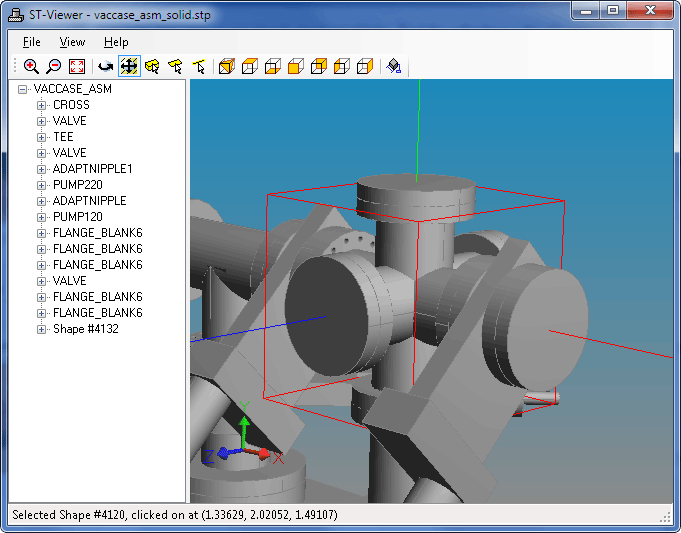
To select elements in the viewer geometry window, first click on
one of the  Pick Body,
 Pick Face, or
  Pick Edge buttons to put the
tool into picking mode. The active mode will be highlighted on the
toolbar, and the cursor will match the mode icon.
Next, simply left-click on an object in the geometry window. Selected shapes are drawn with a red bounding box, faces are drawn in blue with a red bounding box, and edges are drawn in blue. If the selected shape is used several times by an assembly, all uses of it will be highlighted.
The status line at the bottom of the window will show the STEP file instance ID of the selected object, as well as the view coordinates that were clicked. Right-clicking in the geometry window will bring up a context menu that you can use to hide the selected element, change its color, or make it transparent.
