Description
The expgedit tool is the EXPRESS-G diagram viewer and editor. This tool can display the diagrams produced by the express2expg tool. The tool allows you to scroll through the EXPRESS-G data model, follow page references, move groups of objects, and redirect lines between objects.
Command Line (All Platforms)
expgedit [options] [datafile]
The UNIX version of the EXPRESS-G editor recognizes the options shown below. In addition, the tool accepts standard X11 options.
- -bg <color>
- Set the background color. The default is white.
- -pg <color>
- Set the color of the page grids. The default is gray.
The UNIX version must be started on an X11 display running. A color display is recommended for best appearance. If you get a "Cannot open display" message, the tool has been unable to connect to your X server. Check the $DISPLAY environment variable or use the -display option. If necessary, use the xhost utility to enable access to your display server.
The Windows version of EXPRESS-G Editor accepts the options shown below:
- /p <file>
- Print the file to the default printer and exit.
- /pt <file> <printer_driver> <port>
- Print the file to the specified printer and exit. For example, if you had the Adobe Acrobat package installed on your machine, you could run the following to get a PDF version of your diagram:
> expgedit /pt diagram.exg "Acrobat PDFWriter"
Run EXPRESS-G Editor from the Windows Start Menu or can start the it from the command line.
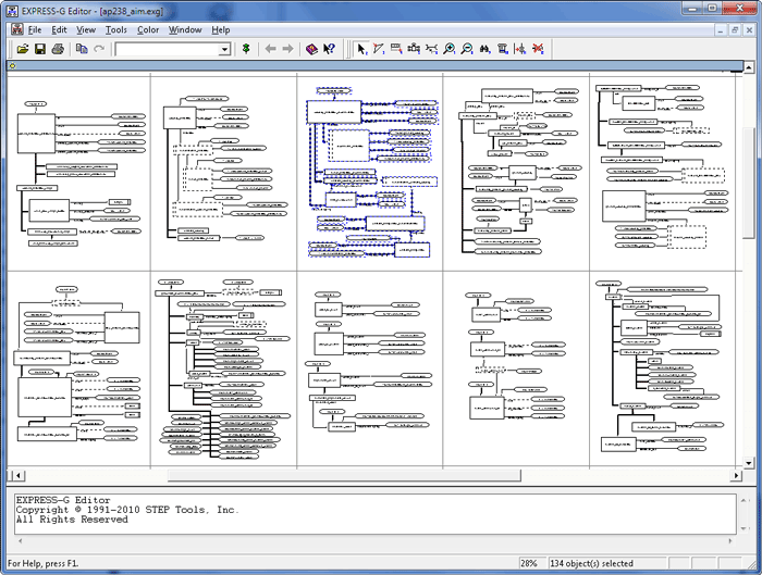
Overview
EXPRESS-G Editor displays diagrams in a large scrolling workspace. Above the workspace are menus and a toolbar. Below the workspace is a status bar that gives the font name/size to use for printing, the page number of the upper right hand corner of the display, and the location of that page in the grid of pages.
The Windows version also contains the message window where information, warning, and error messages are printed. On UNIX systems these messages are printed in the terminal window where the editor was started.
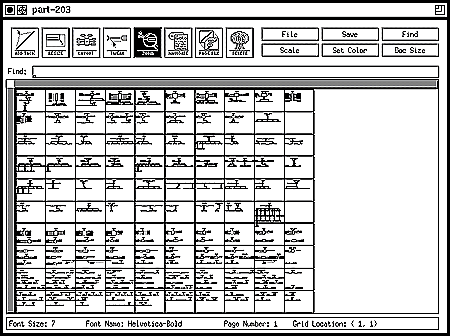
Changing Display Scale
Initially, the workspace is scaled so that you can see the entire diagram. To zoom in:
UNIX
Click the Zoom button on the toolbar. Once this tool is activated you can click in a spot with the second (middle) mouse button to zoom in. To zoom out, click again. You can also choose a scale from the Scale menu.
Windows
Either press <F9> or choose the Toggle Zoom tool on the Tools menu, or choose Scale on the View menu and set scale to 100% in the Scale dialog box. You can also use the Quick Scale menu accessible through the scale indicator located on the status bar:
![]() .
.
Moving through the Diagram
You can move through a diagram using scroll bars, the Panner window (Windows version only), the search box (described in the next section), or by following page references. Page references connect two definitions, such as a super/sub type relationship, without having a line physically connecting them. In addition, there are special methods for navigating between entities in the same inheritance branch and between entities connected by a reference path through attributes.
To use the page references and the special methods to travel around the document, you must first activate the Navigate tool. See Toolbars.
UNIX
Click the Navigate button on the toolbar. Once this tool is activated you can click page references and entities with the second (middle) mouse button.
Windows
Activate the Navigation tool using the toolbar button
 , the Tools |
Navigate command, or the <F10> key. Once the tool is
activated you can click page references and entities with the left
mouse button.
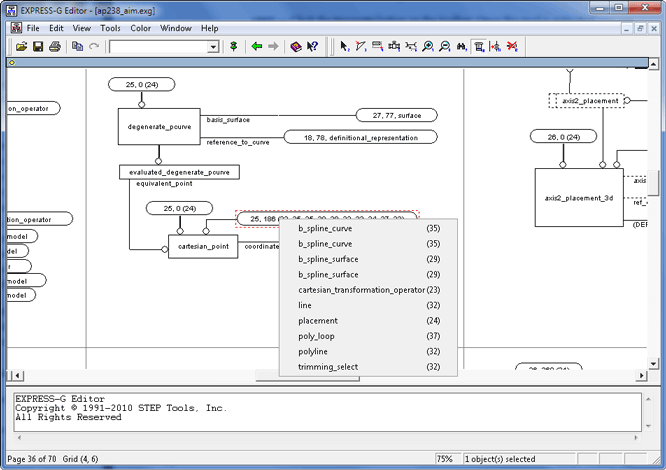
For outgoing page references, you will travel immediately to the other end of the reference. For incoming page references a menu will appear where you can select which page reference you want to visit. This menu is shown above.
For entities, you will travel through two levels of menus, first selecting the type of relationship (forward reference, backward reference, supertype, subtype), then selecting from the resulting list. Reference and inheritance lists are indented representations of a tree, where the greater indentation indicates a further distance in the selected direction. The punctuation in these lists corresponds to the punctuation used in STEP AP Mapping Tables.
| Symbol | Meaning |
|---|---|
. |
Entity to one of its attributes |
-> |
Attribute to its type |
<- |
Attribute type from attribute |
=> |
Supertype to subtype |
<= |
Subtype to supertype |
= |
Select to one of its components |
1=> |
Supertype to a ONEOF subtype |
1<= |
ONEOF subtype to supertype |
(above) |
Duplicate entity, see above |
Navigation Sequence
Windows
The Editor stores the locations where the navigation was initiated, so that you can return to the previous location by using the View | Back command. These stored locations form a navigation sequence that can be traversed back and forth by using the View | Back and View | Forward commands. A navigation sequence is updated by the following operations:
Page reference navigation
Search (Edit | Find and Edit | Find Next commands)
Edit | Go To command
Searching for Definitions
You can also find specific definitions by typing a name or regular expression in the search box at the top of the editor. Pressing <Enter> will scroll the diagram to the first matching definition. The matching definition will be surrounded by a red bounding outline. To find the next match, press <Enter> again or use the View | Find Next command (Windows version only).
The search operaton uses regular expressions. It accepts file name completion syntax (i.e. 'R*' will find any entities, defined types, etc. that have 'R' as their first letter, it is case insensitive). It also offers alternation '[abcd]', and exclusion '[^abcd]'. If you want access to full regular expressions you may enclose the expression in parentheses (i.e. 'R.*' means any entity that starts with 'R.' where as '(R.*)' means any entity that starts with just 'R').
The search can also find entities using Part 21 short names. In order for this method to work there must be a short name file somewhere in your rose search path. Short name files are identified by having the same name as the EXPRESS-G file only with the extension '.nam'.
Selecting Objects in the Workspace
Selecting and moving objects is accomplished using the Select tool. When the Select tool is active and you click an object, that object will become selected and the previous selection will be cleared. To keep the old selection and add a new object to it, hold down <Shift> while selecting the new object. You can also remove objects from the selection by holding down <Shift> and clicking the objects you want to remove. To select a group of objects, click in the diagram blank space and drag out a box that surrounds all of the objects you want to select. Once you selected an object or objects you can drag the selection to a new location.
You can also select larger groups of definitions. Double-click an entity to select the entity and its attached attributes. If you hold down <Ctrl> while you double-click an entity, that box and all of its attached boxes, as well as all of the boxes below it in the inheritance tree will become selected. This is extremely useful for moving entire inheritance trees around.
Windows
When the active tool is other than Select, you can still temporarily use the Select tool by pressing and holding down the <Spacebar> key.
Mouse Operation
Left Mouse Button
UNIX
Always used for selections and dragging (see commands below).
Windows
Always performs whatever action the active tool is programmed to perform. See the tool descriptions for a more detailed information. When the active tool is Select, use the following operaitons.
- Drag
- Make a rectangle, objects that are inside the rectangle will be selected.
- Single-click
- Select the object.
- Double-click
- Select the object as well as any attributes of that object, or edit the bookmark if it is the selected object.
- <Ctrl>+Double-click
- Select the object as well as any attributes of that object, and repeat this for all of the children of this object in the inheritance tree.
When the <Shift> key is held down while making a selection, all of the newly selected objects have their selection state reversed.
Middle Mouse Button
UNIX
This always performs whatever action the active tool is programmed to perform. See the tool descriptions below for a more detailed information.
Windows
If available, the middle button is used for panning. If you hold down the middle button and move the pointer, the diagram will move as if it were attached to the pointer.
Right Mouse Button
Windows
This button always displays the shortcut menu. See Shortuct Menus for more information on shortcut menus.
Wheel button ( IntelliMouse pointing device and compatible devices )
Windows
When pressed, the wheel button works as the middle mouse button. When rotated the wheel button scrolls the diagram (vertically if <Shift> is released or horizontally if <Shift> is held down), and zooms the diagram if the <Ctrl> key is held down.
Restricted Movements
Windows
The restricted movements feature allows you to align and resize objects more accurately. To use this feature, select an object, and then press and hold down the <Alt> key while moving the mouse. If you start moving the mouse horizontally, vertically or in any diagonal direction, the selected object will move only in this direction, regardless of how you continue to move the mouse. For example if you started to move the object in horizontal direction, the vertical coordinate of the object will remain the same while you hold the <Alt> key even if the mouse pointer moves in vertical direction.
The Workspace
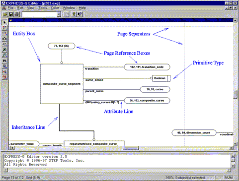
The workspace is a scrolling work area containing an EXPRESS-G diagram. The diagram is marked with a light grey grid to indicate where the page boundaries will be when the file is printed. The figure below shows an example of this. A box or line that crosses a page separator will be split across multiple pages. You can reposition objects or insert page breaks as needed to prevent this.
Menus (Windows Version)
Each of the sections below describes a menu and the commands which appear on it. Some of these commands are also available on one of the toolbars, or may have a keyboard shortcut. We have shown toolbar icons and keyboard shortcuts where appropriate
File Menu
 Open
Open
(Also <Ctrl+O>) Shows the Open File dialog box. Using this dialog box you can browse the file system and locate the file to open.
Close
Closes the active diagram window. If the diagram was modified,
EXPRESS-G Editor will prompt whether to save the diagram or not.
 Save
Save
(Also <Ctrl+S>) Saves the active diagram in the file it was opened from.
Save As
displays the Save As dialog box. You can then select a file to which you want to save the active diagram or type a new file name.
 Print
Print
(Also <Ctrl+P>) displays the Print dialog box, where you may specify the range of pages to be printed, the number of copies, the destination printer, and other printer options.
When you have objects selected in the diagram, only these objects will be printed by default (the Selection option under Print Range is selected). Click All under Print Range if you want the whole diagram to be printed.
If the command is carried out by the toolbar button it does not display the Print dialog, but starts printing immediately.
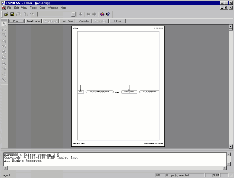
Print Preview
Displays the diagram in the preview window exactly as it would be printed on paper as shown below. This way you can check your layout before you actually start printing.
Print Setup
Use this command to select a printer and a printer connection. This command displays the Print Setup dialog box, where you specify the printer and its connection.
Page Setup
Use this command to specify the headers and footers on a page. This command displays the Page Setup dialog box (see below).
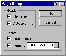
This dialog has the following options for the header and footer:
- File Name -- Select to print the file name in the upper-left corner of a page.
- Date and time -- Select to print the time of printing in the upper-right corner of a page.
- Page number -- Select to print the page number and grid location in the lower- left corner of a page.
- Remark -- Print a remark (the product name by default) in the lower-right corner of a page. You can type the text of the remark in this box. It also keeps a history list of previously used remarks, to open the list click the
Send
Use this command to send the active diagram through e-mail. This command displays a message window of your default e-mail program with a blank e-mail message and the active diagram as an attachment. You can then use your e-mail program to send the message.
Recent files
These items correspond to the most recently opened files. Choose one of these to open the file immediately.
Exit
Quits EXPRESS-G Editor.
Edit Menu
 Copy
Copy
(Also <Ctrl+C>) Copies the selected objects to the Clipboard using the Windows Metafile format. The objects can be pasted into any Windows application that supports this format. The example below was copied from one of the STEP APs.

Some publishing programs allow you to edit each graphical object in the pasted data, e.g. to set font, line style and thickness, shading, etc.
Save Selection As
Saves the selected portion of the diagram to a file for later import into a document. You can save the selection as a Windows Metafile (.wmf) or Encapsulated PostScript (.eps) file. The EPS produced by the EXPRESS-G Editor does not include TIFF preview.
Select All
(Also <Ctrl+A>) Selects all objects in the diagram. Selected objects are displayed with the blue bounding outline.
Find
(Also <Ctrl+F> and
![]() ) This command is used to find objects in the diagram using regular expressions. When selected it displays the Find dialog box (see below).
) This command is used to find objects in the diagram using regular expressions. When selected it displays the Find dialog box (see below).

To find an object in the diagram type the regular expression in the Object name box or use the list to select one of the previously used. To open the list, click the
![]() button. For more information on regular expressions see Searching for Definitions.
button. For more information on regular expressions see Searching for Definitions.
 Find Next
(Also <Ctrl+Right Arrow>) Use this command to find the next box matching the current search pattern.
Go To
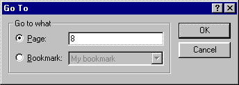
(Also <Ctrl+G>) This command displays the Go To dialog box shown below. Use this dialog box to specify a page or bookmark in the diagram and scroll the diagram instantly to display the specified location
.
 Insert Bookmarks
Use this command to insert bookmarks in the diagram. When this command is chosen the pointer becomes a
![]() .
.
Click in the diagram to insert a new bookmark. EXPRESS-G Editor shows a text input box where you clicked. Type the bookmark text and press <Enter>. The bookmark will be displayed at the same place.
You can move the bookmark by selecting and dragging it to the new location when the active tool is Select. You can edit the bookmark text by right-clicking it and choosing the Edit Bookmark command on the Object shortcut menu. You can delete a bookmark by choosing Delete Bookmark on the Object shortcut menu.
The bookmarks can be displayed as pushpins and labels or as pushpins only. They also can be hidden so that they are neither displayed nor printed. The View | Bookmarks menu commands control how the bookmarks are displayed.
Remove All Bookmarks
Removes all bookmarks from the diagram.
Add Row
Adds a new row of pages to the bottom of the diagram.
Insert Row
Inserts a new row of pages at the top of the diagram. All objects in the diagram are shifted down by one page.
Add Column
Adds a new column of pages to the right of the diagram.
Insert Column
inserts a new column of pages at the left side of the diagram. All objects in the diagram are shifted right by one page.
Remove Row
Removes the last row of pages. The pages in this row should not contain any objects, otherwise it will not be removed.
Remove Column
Removes the last column of pages. The pages in this column should not contain any objects, otherwise it will not be removed.
Properties
(Also <Alt+Enter>) This command displays the Diagram Properties dialog box shown below. The following options are available:
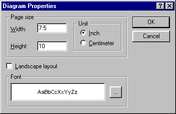
- Page size and orientation. You can set the width and height of a page in either inches or centimeters. When you select the Landscape layout check box the width and height values will swap.
- Font specifications. Click the [...] button to display the Font dialog box that you can use to select any font installed on your system with any attributes, such as bold, italic, color, underline, and overstrike. These font specifications are not recognizable by the UNIX version of the editor -- it will continue to use the default font (Helvetica Bold).
View Menu
Commands in this menu control the appearance of both the main window and a diagram window.
Toolbars
Displays a menu with the following commands:
- Standard -- Displays or hides the standard toolbar, which includes buttons for some of the most common commands in EXPRESS-G Editor. The standard toolbar is normally located across the top of the main window, under the menu bar.
- Diagram Tools -- Displays or hides the Diagram Tools toolbar, which includes buttons for the tools from the Tools menu.
- Large Buttons -- Enlarges the toolbar buttons so that they are easier to see. This command is useful when giving presentations or for those who have poor vision.
Status Bar
Displays or hides the status bar at the bottom of the main window. Status bar describes the action to be executed by the selected menu command or toolbar button, and the keyboard latch state. It also shows the current page number and its grid location when the pointer is over the diagram workspace, as well as the current scale and the number of currently selected objects.You can also set the scale using the Quick Scale menu which is displayed when you click on the scale indicator
![]() on the status bar.
on the status bar.
Messages
Displays or hides the message window located at the bottom of the main window. Information, warning, and error messages appear in this window during the tool operation. You can also resize this window vertically by dragging its resize bar with the mouse.
All Diagram
(Also <Ctrl+L>) Scales the diagram to fit everything into the diagram window.
Full Size
(Also <Ctrl+U>) Displays the diagram in full size (scale of 100%).
Panner
(Also <Ctrl+R>) Displays or hides the Panner window shown below. The Panner window is like a two-dimensional scrollbar. When you drag the floating box in the window, the diagram will scroll accordingly. The aspect ratio of the Panner window is the same as the aspect ratio of the diagram, while the aspect ratio of the floating box is that of the diagram window.

Forward
(Also <Alt+Right Arrow>) Scrolls the diagram to the next location in the navigation sequence. If the end of the sequence is reached this command becomes unavailable. See Navigation Sequence for more information.
Back
(Also <Alt+Left Arrow>) Scrolls the diagram to the previous location in the navigation sequence. If the beginning of the sequence is reached this command becomes unavailable. See Navigation Sequence for more information.
Bookmarks
Displays a menu with the following commands:
- Pushpins and Labels -- Displays full bookmarks (as pushpins and labels).
- Pushpins Only -- Displays bookmarks only as pushpins (no text labels).
- Hide All -- Hides all bookmarks without actually removing them.
Page Grid
Displays or hides the page grid. If the grid is displayed in the window, it will also be printed as a thin frame around each page. If the grid is hidden, the pages will be printed without frames.
Partial Model
This command controls the appearance of the primitive type boxes in the diagram. When this command is checked the primitive type (e.g. REAL,
LOGICAL, etc.) boxes are hidden.
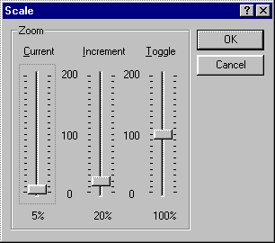
Scale
Displays the Scale dialog box shown below. This dialog box has three sliders that control the current scale, the increment scale (used by the Zoom In/Out tools) and the toggle scale (the second scale used by the Toggle Zoom tool).
The default values are:
- Current scale -- set to fit the whole diagram.
- Increment scale -- 20%
- Toggle scale -- 100%
Working Set
Displays the Working Set dialog box, which you can use to view, edit, and apply the working set.
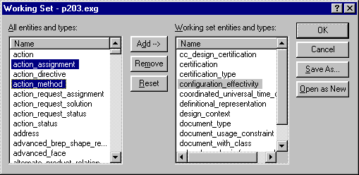
This dialog box has two lists that are used to manipulate the working set. The All entities and types list contains names of all entities in the current diagram. The Working set entities and types list contains the names of entities included in the working set. You can add entities to the working set by selecting them in the All entities and types list and dragging them to the Working set entities and types list or clicking the Add button. To remove entities from the working set select them in the Working set entities and types list and then click Remove. To remove all entities from the working set click Reset.
To save the working set in a file click the Save As button. This will display the Save As dialog box. You can save the working set either as a working set text file or as an EXPRESS-G diagram. If the working set is saved in the text file this file can be later used by EXPRESS Compiler or the EXPRESS-G Layout tool. Click the Open As New button to generate a new EXPRESS-G diagram using the specified working set and then load this diagram into the editor. The new diagram name will be constructed from the name of the active diagram by adding the _ws_# suffix, where the # is a number 1, 2, etc. For example if the original diagram was named MyDiagram.exg, then the new diagram will be named MyDiagram_ws_1.exg.
Click OK to close the dialog box and apply the changes in the working set to the current diagram (all entities in the working set will be marked by the working set color). Click Cancel to close the dialog box and ignore the changes.
Tools Menu
The commands in this menu activate different tools used to edit the diagram.
 Select
(Also <F2>) Activates the Select tool, which is used to select and move objects. When this tool is activated the pointer becomes an
![]() . See Selecting Objects in the Workspace for more information.
. See Selecting Objects in the Workspace for more information.
 Add Tack
(Also <F3>) Activates the Add Tack tool. The Add Tack tool can be used to create new tacks on existing lines. When the tool is activated the mouse pointer becomes a
![]() .
.
To create a new tack click the line to which you wish to add a tack and drag the tack to the desired location.
 Resize
(Also <F4>) Activates the Resize tool. The Resize tool is used to resize boxes. When this tool is activated the mouse pointer becomes a
![]() .
.
To resize a box click in the box and drag the border of the box to the desired size.
 Layout
(Also <F5>) Activates the Layout tool. The Layout tool reformats the boxes that are connected to an entity. When this tool is activated the mouse pointer becomes an
![]() .
.
When you click an ENTITY, ENUMERATION, or defined type box the following menu appears:
- All Attributes to the Left -- Lays out all attribute boxes on the left side of the entity/type box.
- All Attrubutes to the Right -- Lays out all attribute boxes on the right side of the entity/type box.
- Attributes Alternate Sides -- Lays out all attribute boxes evenly on the left and right of the entity/type box.
- Custom -- Lays out each connected box separately using the Custom Layout dialog box.
When you click a SELECT type box the menu will have these additonal commands:
- Fan-out Above -- Lays out the boxes of the select list in a fan-like fashion above the SELECT box.
- Fan-out Below -- Lays out the boxes of the select list in a fan-like fashion below the SELECT box.
This tool can also be used to reestablish the Manhattan layout of lines. If you click a line, the following menu appears:
- Lay out Entire Line -- Delete all tacks and apply the Manhattan layout.
- Lay out Line Segment -- Apply the Manhattan layout to the selected line segment (between the two closest tacks).
If you click a forked tack, the Lay out Entire Line command will lay out the whole tree of lines.
Custom Layout Dialog Box
The Custom Layout dialog box is shown below.
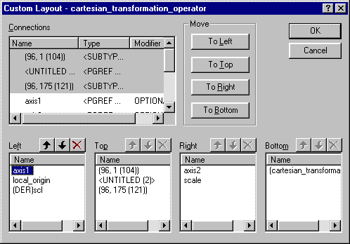
The Custom Layout dialog box has five lists -- one that contains all connections of the selected entity/type box, and four lists for each side of the entity box. You can lay out connections by selecting them in the Connections list and then moving them to the side boxes. To move you can either click the corresponding button in the Move area or simply drag the selected item(s) into one of the side boxes. You can also drag items between side boxes.
The Connections list has three columns. The Name column contains the names of the connections (attribute name, page references or sub/supertype name). The Type column contains the types of connections (attribute type, page reference to/from, or sub/supertype relationship). The Modifier column contains the additional connection properties, such as OPTIONAL, INVERSE or DERIVED for attributes. To sort the list according to a column click the column header. To change the width of a column drag the column separator. To adjust the width automatically, double-click the column separator. This will change the width to accommodate the widest item.
Each of the side lists has only one column. You can sort them the same way by clicking the column header, or move items using the
![]() and
and
![]() buttons at the top of the list. The connections will be laid out according to the order in the side lists -- the top and bottom connections will be placed from left to right, and the left and right connections from top to bottom.
buttons at the top of the list. The connections will be laid out according to the order in the side lists -- the top and bottom connections will be placed from left to right, and the left and right connections from top to bottom.
 Move Label
(Also <F6>) This command activates the Move Label tool. This tool is used to relocate text labels. When the tool is active the mouse pointer becomes an
![]() .
.
Use this tool by clicking tacks on the line you want to move the label for. The label will jump to the current pointer location from which you can drag the label out to the new location.
 Zoom In
(Also <F7>) This command activates the Zoom In tool. This tool increases the scale of the diagram by the scale increment set in the Scale dialog box. The default value of the scale increment is 20%.
To zoom in click anywhere in the diagram. When the scale changes, the place on the diagram under the pointer is kept as constant as possible, providing the more detailed view of the specified location.
 Zoom Out
(Also <F8>) This command activates the Zoom Out tool. This tool decreases the scale of the diagram by the scale increment set in the Scale dialog box. The default value of the scale increment is 20%.
To zoom out just click in the diagram. When the scale changes, the place on the diagram under the mouse pointer is kept as constant as possible, providing the wider view of the surroundings of the specified location.
 Toggle Zoom
(Also <F9>) This command activates the Toggle Zoom tool. The tool switches the scale of the diagram between the current scale and the other one set in the Scale dialog box as the Toggle scale (100% by default). When this tool is activated and the current scale is smaller than the toggle scale the pointer becomes a
![]() , if the current scale is larger than the toggle scale the pointer becomes an
, if the current scale is larger than the toggle scale the pointer becomes an
![]() .
.
To switch the scale click in the diagram. Click again to return to the previous scale. When the scale changes, the place on the diagram under the mouse pointer is kept as constant as possible, providing the more detailed or wider view of the specified location.
 Navigate
(Also <F10>) This command activates the Navigate tool. This tool is used to quickly navigate page references and inheritance trees. When this tool is activated the mouse pointer becomes a
![]()
When you click a page reference, the tool will either scroll the diagram immediately to make the referred box visible, or if the page reference box refers to multiple objects, the tool will display a menu or a list box containing references you can follow.
When you click an entity box, the tool will display the following menu:
- Forward References -- Displays a menu or a list box containing all the forward page references of the selected entity.
- Backward References -- Displays a menu or a list box containing all the backward page references of the selected entity.
- Subtypes -- Displays a menu or a list box containing all the subtypes of the selected entity.
- Supertypes -- Displays a menu or a list box containing all the supertypes of the selected entity.
If you click in the blank space, the tool will display the menu to navigate all the root objects in the diagram:
- Inheritance Roots -- Displays a menu or a list box containing all the inheritance root objects (the objects that do not have supertypes).
- Reference Roots -- Displays a menu or a list box containing all the reference root objects (the objects that are not attributes of other objects).
Reference and inheritance menus and lists are indented representations of a tree, where the greater indentation indicates a further distance in the selected direction. The punctuation in these lists corresponds to the punctuation used in STEP AP Mapping Tables (see table on See Also: Symbol).
 Page Reference
(Also <F11>) This command activates the Page Reference tool that is used to insert page references. When the tool is activated the mouse pointer becomes a
![]() .
.
To insert a page reference click the line you want to have a break in. It is also possible to break off all the children of an inheritance by clicking the tack where all the children split off (called a forked tack). Please note that there are several restrictions to where page references can be inserted. The two most common problems are: you can not insert a page reference before the forked tack, and you can not have more than one page reference on a line.
 Remove
(Also <F12>) This command activates the Remove tool. The Remove tool is used to remove unwanted tacks and page references from the diagram. When the tool is activated the mouse pointer becomes a
![]() .
.
To use this tool simply click the object to be deleted. If the object is a page reference onto the page the tool will display a menu of references that may be deleted. Choose a reference from the menu and the reference count will be reduced by one. When the reference count reaches zero, the page reference box will be removed.
If the object is a page reference from the page the tool will display the following menu:
- Delete Only -- Deletes the page reference box.
- Delete and Yank -- Deletes the page reference box and moves (yanks) the referred box close to the referring box.
Color Menu
This menu has five color commands for each of the possible object colors. To change the color of an object, select it and then choose one of the menu colors.
It also has the Working Set command that is used to include the colored objects in the working set.
Window Menu
This menu contains commands for window control. EXPRESS-G Editor allows you to open several files at once, each of them placed in a separate window. The following commands are available through this menu:
Cascade
Arranges the windows in an overlapped fashion, so that all title bars are visible.
Tile
Arranges multiple opened windows vertically in a non-overlapped fashion.
Arrange Icons
Arranges the icons for minimized windows at the bottom of the main window. If there is an open document window at the bottom of the main window, then some or all of the icons may not be visible because they will be underneath this document window.
Split
Splits the active window into two panes. You may then use the mouse or the arrow keys to move the splitter bar. When the splitter bar is in the desired position, click or press <Enter> to set the splitter bar in its new position. Press <Esc> to keep the splitter bar in its original position.
Using split configuration you can view two parts of the same diagram at once, perhaps with different scales, so that the part with the smaller scale can serve as a map to the other part. The figure below shows a split window with two views of the same diagram.
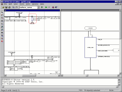
The area outlined in the rounded box on the left pane is shown on a large scale (150%) on the right pane.
Clear Messages
Clears the contents of the message window.
Window 1, 2...
EXPRESS-G Editor displays a list of currently open diagram windows at the bottom of the Window menu. A check mark appears next to the diagram name of the active window. Choose a window from this list to make it active.
Help Menu
Commands in this menu are used to access the help system.
EXPRESS-G Editor Help
(Also <F1>) This command displays the context-sensitive Help, which is the help information relevant to the current program context -- active window, menu, dialog box, etc.
 Contents and Index
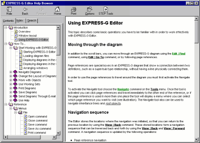
(Also <Ctrl+F1>) Displays the Help browser shown below. The Help browser is used to navigate through Help topics using table of contents, index, text search, and navigation buttons.
 What's This?
(Also <Shift+F1>) This command puts EXPRESS-G Editor into the Help mode.
This command will change the mouse pointer to an
![]() to indicate that the editor is in the Help mode. Click a menu command, toolbar button, or click in a part of the main window to get information about this command, button, or window part.
to indicate that the editor is in the Help mode. Click a menu command, toolbar button, or click in a part of the main window to get information about this command, button, or window part.
STEP Tools on the Web
Displays a menu with the following commands:
- STEP Tools Home Page -- Starts your default browser and connects to the STEP Tools, Inc. homepage.
- Products -- Starts your default browser and connects to the STEP Tools, Inc. products page.
- Support -- Starts your default browser and connects to the STEP Tools, Inc. technical support page.
About EXPRESS-G Editor
Displays the copyright notice, version number and the license information of your copy of EXPRESS-G Editor.
Shortuct Menus
Shortcut menus appear when you right-click or press the Application key (
![]() ). There are two types of shortcut menus provided by EXPRESS-G Editor -- the
). There are two types of shortcut menus provided by EXPRESS-G Editor -- the
Object menu and the Diagram menu.
The Object Shortcut Menu
The Object menu appears when you right-click an object in the diagram. This menu has the following commands:
Copy
Copies the selected object(s) to the Clipboard.
Edit Bookmark
Creates a text input box to edit the selected bookmark (This command is on the menu only if the selected object is a bookmark.)
Delete Bookmark
Deletes the selected bookmark. (This command is on the menu only if the selected object is a bookmark.)
Add to Working Set
Adds selected entities/types to the working set. (This command is on the menu only if the selection contains entity and/or type boxes.)
View Working Set
Displays the Working Set dialog box to view, edit, and apply the working set. (This command is on the menu only if the selection contains entity and/or type boxes.)
Select
Activates the Select tool.
Add Tack
Activates the Add Tack tool.
Resize
Activates the Resize tool.
Layout
Activates the Layout tool.
Move Label
Activates the Move Label tool.
Zoom In
Activates the Zoom In tool.
Zoom Out
Activates the Zoom Out tool
Toggle Zoom
Activates the Toggle Zoom tool.
Navigate
Activates the Navigate tool.
Page Reference
Activates the Page Reference tool.
Remove
Activates the Remove tool.
Color
Opens the Color Menu.
Scale
Displays the Scale dialog box.
All Diagram
Scales the diagram to fit everything into the diagram window.
Full Size
Displays the diagram in full size (scale of 100%).
EXPRESS Source
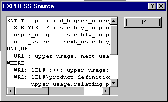
Displays the EXPRESS Source dialog box with the EXPRESS language definition of the currently selected object. (This command is on the menu only if the selected object is an ENTITY or TYPE box.
Show this on the other pane
Scroll the other pane to show the same place on the diagram that is being shown on the active pane. (This command is on the menu only if the active diagram window is split.)
This command provides a quick way to see a specific place in a diagram. When the window is split and one pane has larger scale than the other, and you click on a diagram in the pane with smaller scale, then if you select this command the same place of the diagram will be shown on the other pane with the larger scale providing more detailed view.
The Diagram Shortcut Menu
The Diagram menu appears when you right-click in the blank space of the diagram. This menu has the following commands:
Show this on the other pane
See above.
Select
Activates the Select tool.
Add Tack
Activates the Add Tack tool.
Resize
Activates the Resize tool.
Layout
Activates the Layout tool.
Move Label
Activates the Move Label tool.
Zoom In
Activates the Zoom In tool.
Zoom Out
Activates the Zoom Out tool
Toggle Zoom
Activates the Toggle Zoom tool.
Navigate
Activates the Navigate tool.
Page Reference
Activates the Page Reference tool.
Remove
Activates the Remove tool.
Scale
Displays the Scale dialog box.
All Diagram
Scales the diagram to fit everything into the diagram window.
Full Size
Displays the diagram in full size (scale of 100%).
Properties
Displays the Diagram Properties dialog box.
Quick Scale Menu
This menu is displayed when you click the scale indicator
![]() located on the status bar.
located on the status bar.
The Quick Scale menu contains the following commands.
200%
Changes scale to 200% (2 times magnification).
150%
Changes scale to 150% (1 1/2 times magnification).
125%
Changes scale to 125% (1 1/4 times magnification).
100%
Changes scale to 100% (normal size).
75%
Changes scale to 75% (3/4 of normal size).
50%
Changes scale to 50% (1/2 of normal size).
25%
Changes scale to 25% (1/4 of normal size).
Fit
Changes the scale to fit the whole diagram into the window.
Menus (UNIX Version)

The menu commands do useful things to the document, such as changing the number of pages, the current scale, or finding an entity or attribute. Menu options that have ellipses '...' after them will bring up a dialog box.
 |
From this menu you can open, close, and save EXPRESS-G diagrams or
you can exit the application.
Save -- Save the EXPRESS-G document in the window that the menu item was selected from. This overwrites the old version of the document. Close -- Close the EXPRESS-G window. Open... -- Open an EXPRESS-G file in a new window. Exit... -- Close all EXPRESS-G windows and exit. |
 |
Save any changes to the document. Overwrites the old version of the document. This is equivalent of the Save comand under the File menu. |
 |
This will search for objects using the criteria in the find edit box. Hitting the return key in the edit box will produce the same results. The object that matches the string will be surrounded by red. In addition the editor will center the object in the middle of the scrolled area. |
 |
Change the viewing magnification. The last item in the menu
allows you to adjust the resolution exactly.
2.0 (double size) ... 0.125 (1/8th size) -- View the diagram at a range of pre-defined magnifications. Fit all on Screen -- Adjust the resolution so the entire diagram is visible. Any Scale... -- View diagram at an arbitrary magnification. This operation also provides direct access to the alternate scale used by the zoom tool. |
 |
Apply colors to objects in the document. When a color is chosen,
all currently selected items are given the color.
No Color - Sets selected items to black (foreground color) Color 1 (Blue) - Sets selected items to blue. Color 2 (Green) - Sets selected items to green. Color 3 (Red) - Sets selected items to red. Color 4 (Gray) - Sets selected items to gray. |
 |
This brings up a menu where you can add and delete pages from the
right and bottom of the document. Note that the entire row or column
of pages must be empty in order to delete it.
Add Row - This will add a row of pages along the bottom of the document. Add Column - This will add a column of pages along the right edge of the document. You should take note of the fact that this will change the page numbers on all of the pages (and page references) for all pages after the first row. Delete Row - This will delete a row from the bottom of the document. For this operation to succeed you must move all objects out of the row to be deleted. Delete Column - This will delete a column from the right edge of the document. For this operation to succeed you must move all objects out of the row to be deleted. Also be aware that this will change most of the page numbers. |
Toolbars
Windows Toolbar
The Windows version has three toolbars: the standard toolbar normally placed across the top of the main window, under the menu bar, the Diagram Tools toolbar normally placed at the left side of the main window, and the Print Preview toolbar, which is visible only in the print preview mode. The standard and Diagram Tools toolbars can be attached to any of the four sides of the window, or left floating free on the desktop.
To move a toolbar to a new location, click the toolbar handle
![]() , and then drag the toolbar. While dragging, you will see the outline of the toolbar. If this outline is thick, it means that releasing the mouse button will leave the toolbar floating, if this border is thin, the toolbar will be attached to the nearest window side.
, and then drag the toolbar. While dragging, you will see the outline of the toolbar. If this outline is thick, it means that releasing the mouse button will leave the toolbar floating, if this border is thin, the toolbar will be attached to the nearest window side.
The toolbar buttons provide quick mouse access to menu commands. The toolbar buttons and their corresponding commands are described below.
Standard Toolbar
The standard toolbar contains basic commands from the File, Edit and Help menus.
| Click | To |
|---|---|
 |
Open an existing diagram. |
 |
Save the active diagram. |
 |
Print the active diagram. |
 |
Copy selected objects to the Clipboard. |
 |
Find the next box matching the pattern. |
 |
Type the search pattern. |
 |
Insert bookmarks in the diagram. |
 |
Go to the previous location in the navigation sequence. |
 |
Go to the next location in the navigation sequence. |
 |
Display the Help browser. |
 |
Put the editor into the Help mode. |
The Diagram Tools Toolbar
This toolbar provides quick mouse access to the diagram tools in EXPRESS-G Editor.
| Click | To |
|---|---|
 |
Activate the Select tool. |
 |
Activate the Add Tack tool. |
 |
Activate the Resize tool. |
 |
Activate the Layout tool. |
 |
Activate the Move Label tool. |
 |
Activate the Zoom In tool. |
 |
Activate the Zoom Out tool. |
 |
Activate the Toggle Zoom tool. |
 |
Activate the Navigate tool. |
 |
Activate the Page Reference tool. |
 |
Activate the Remove tool. |
The Print Preview Toolbar
The Print Preview toolbar offers the following commands.
| Click | To |
|---|---|
| Display the Print dialog box and start a print job. | |
| Next Page | Preview the next printed page. |
| Prev Page | Preview the previous printed page. |
| One Page/Two Page | Preview one or two printed pages at a time. |
| Zoom In | Take a closer look at the printed page. |
| Zoom Out | Take a larger look at the printed page. |
| Close | Return from print preview to the editing window. |
UNIX Toolbar
The tool bar is located at the upper left of the window. When the program first starts up the Zoom tool will be selected. You can always tell what tool is selected because it will appear inverted from the rest of the tool buttons. The selected tool takes over the second (middle) mouse button.
 |
The Add Tack tool creates new tacks on existing lines. Press the mouse button with the pointer over the line which you wish to add a tack to. Then while still holding the mouse button down drag the pointer to the desired location for the new tack. Then release the mouse button. |
 |
The Resize tool resizes boxes. Press the mouse button inside of a box and then drag the outline to the desired size. |
 |
The Layout tool rearranges the lines and boxes so they
looks similar to the layout originally created by express2expg.
Press the mouse button over an entity. A menu will appear with
choices for placing all attributes on the left, all on the right or on
alternate sides. Select an option and release the mouse button.
This tool can also clean up lines. Press the mouse button on a line. A menu will appear that offers you the choice of laying out the entire line or just the segment you clicked on. If you select the segment, it will update the line segment between the two closest points. If you select the whole line, it will delete any tacks you may have added and then re-layout the line. If you press the mouse button on a forked tack it will layout all of the surrounding lines. |
 |
The Tweak tool repositions a label for a line. This is done by pressing the mouse button when the mouse is over any of the tacks on the line you want to move the label for. The label will jump to the current pointer location from which you can drag the label out to the desired new location. |
 |
The Zoom tool toggles between two resolutions (the resolutions can be set by using the Any Scale menu option under the Scale menu talked about above, they default to 1.0 and fit all on screen). Also it will highlight the box, line or point that was under the mouse when the button was pressed. |
 |
The Page Reference Navigation tool traverses page references. When you click on a page reference you either immediately move to the box the page reference refers to, or if the page reference box refers to multiple objects a menu is brought up which allows you to select which reference you want to follow. |
 |
The Page Break tool inserts page references. Click on the line you want to break. It is also possible to break off all the children of an inheritance by simply clicking on the tack where all the children split off (called a forked tack). There are some restrictions to where page breaks can be inserted. In particular, you can not insert a page break before the forked tack, and you can not have more than one page break on a line. |
 |
The Delete tool allows you to remove unwanted tacks and
page breaks from the diagram. Simply press the mouse button when the
mouse is over the entity to be deleted. In the case of a page
reference box if there are multiple objects that reference it you will
be given a menu of objects that may be deleted.
When the page reference refers to another entity a menu will give you the option of simply deleting the page reference box, or deleting the box and moving (or yanking) the object it refers to, to the location of the page reference (be careful when deleting and yanking). |
Keyboard Shortcuts
The following keyboard commands can be used with the Windows version of EXPRESS-G Editor.
| Use | To |
|---|---|
| Left Arrow | Scroll left one position (the same as the
 scrollbar button). If <Scroll Lock> is on, move the
mouse pointer left one pixel instead of scrolling.
|
| Alt+Left Arrow | Go to the previous location in the navigation sequence. |
| Right Arrow | Scroll right one position (the same as the
 scrollbar button). If <Scroll Lock> is on, move the
mouse pointer right one pixel instead of scrolling.
|
| Ctrl+Right Arrow | Find the next box matching the search pattern. |
| Alt+Right Arrow | Go to the next location in the navigation sequence. |
| Up Arrow | Scroll up one position (the same as the
 scrollbar
button). If <Scroll Lock> is on, move the mouse pointer
up one pixel instead of scrolling. scrollbar
button). If <Scroll Lock> is on, move the mouse pointer
up one pixel instead of scrolling. |
| Down Arrow | Scroll down one position (the same as the
 scrollbar button).
If <Scroll Lock> is on, move the mouse pointer down one
pixel instead of scrolling. scrollbar button).
If <Scroll Lock> is on, move the mouse pointer down one
pixel instead of scrolling. |
| Home | Scroll left one screen. If <Scroll Lock> is on, move the mouse pointer left ten pixels instead of scrolling. |
| Ctrl+Home | Scroll all the way to the left. |
| End | Scroll right one screen. If <Scroll Lock> is on, move the mouse pointer right ten pixels instead of scrolling. |
| Ctrl+End | Scroll all the way to the right. |
| Page Up | Scroll up one screen. If <Scroll Lock> is on, move the mouse pointer up ten pixels instead of scrolling. |
| Ctrl+Page Up | Scroll all the way to the top. |
| Page Down | Scroll down one screen. If <Scroll Lock> is on, move the mouse pointer down ten pixels instead of scrolling. |
| Ctrl+Page Down | Scroll all the way to the bottom. |
| Ctrl+Insert | Copy the selection to the Clipboard. |
| Spacebar | Simulate the mouse click if the <Scroll Lock> is on. |
| Ctrl+Tab | Switch to the next open diagram window. |
| Ctrl+Shift+Tab | Switch to the previous open diagram window. |
| Ctrl+A | Select all objects in the diagram. |
| Ctrl+C | Copy the selection to the Clipboard. |
| Ctrl+F | Find a box using a search pattern. |
| Ctrl+G | Go to a page or bookmark. |
| Ctrl+L | Scale the diagram to fit it whole into the window. |
| Ctrl+O | Open an existing EXPRESS-G diagram. |
| Ctrl+P | Print the active diagram. |
| Ctrl+S | Save the active diagram to the same file it was opened from. |
| Ctrl+R | Show or hide the Panner window. |
| Ctrl+U | Set the diagram scale to 100%. |
| Ctrl+W | View and edit the working set. |
| F1 | Get help on the current context. |
| Ctrl+F1 | Display the Help browser. |
| Shift+F1 | Put the editor into the Help mode. |
| F2 | Activate the Select tool. |
| F3 | Activate the Add Tack tool. |
| F4 | Activate the Resize tool. |
| Ctrl+F4 | Close the active diagram window. |
| Alt+F4 | Quit the editor. |
| F5 | Activate the Layout tool. |
| F6 | Activate the Move Label tool. |
| Ctrl+F6 | Switch to the next open diagram window. |
| Ctrl+Shift+F6 | Switch to the previous open diagram window. |
| F7 | Activate the Zoom In tool. |
| F8 | Activate the Zoom Out tool. |
| F9 | Activate the Toggle Zoom tool. |
| F10 | Activate the Navigate tool. |
| Shift+F10 | Display the shortcut menu. |
| F11 | Activate the Page Reference tool. |
| F12 | Activate the Remove tool. |
| Alt+Enter | Edit diagram properties. |
Application key  |
Display the shortcut menu. |
Customizing
This section applies only to the UNIX version of the EXPRESS-G editor.
The expgedit editor is an Xt application. Any Xt application can be visually customized through the use of resource files. A sample resource file can be found in $ROSE/etc/Expgedit. This file describes the defaults that are compiled into the tool. You can customize this file and then tell the X server to use it by typing:
% xrdb -merge <filename>
Or set the $XAPPLRESDIR environment variable to directories containing resource files:
% setenv XAPPLRESDIR /directory_one:/directory_two
If you have some prior experience with Xt, you may find the widget tree for the tool to be useful:
    Expgedit (applicationShell)
        TopLevelShell
        	main (form)
        	titleBar (box)
        		tools (box)
        			createTack_button (command)
        			boxResize_button (command)
        			layoutBox_button (command)
        			tweakLabel_button (command)
        			zoomView_button (command)
        			pageRefNavigation_button (command)
        			createPageRef_button (command)
        			deleteObj_button (command)
        		buttons (box)
        			file (menu button)
        			save (command)
        			find (command)
        			scale (menu button)
        			color (menu button)
        			docsize (menu button)
        	editLabel (label)
        	edit (text)
        	scrolled (viewport)
        		canvas (simple)
        			menu (simpleMenu)
        				entry0 (smeBSB)
        				entry1 (smeBSB)
        				  .
        	infoLabel (label)