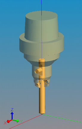
 In order to fully simulate machining, your STEP-NC data should include
a CAD description of each tool used by the process. The model can be
an AP203 or AP214 file from any CAD system. The origin of the model
should be at the tip of the cutting tool.
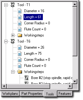
First, indicate the tool that you want to add shape to, either by clicking in the Workplans tab on a workingstep that uses the tool, or by clicking in the Tools tab (see image below) on the entry for the actual tool. Next, select the File | Import | Tool Shape ... menu entry and use the file dialog to pick the appropriate STEP file.
To get you started, the STEP-NC Machine installation directory under "Program Files" contains a "tools" subdirectory with a sampling of STEP files for various inch and millimeter tools.
Once you have a CAD shape, you may need to adjust the tool length parameter so that it simulates properly with the machine tool models. In the Tools tab (see image below), right click on the "Length" entry for the tool and select Edit Nominal Value. This length determines where the shape is placed when mating it with the spindle of a machine tool model.
